
Camera anti-shake structure

A camera and anti-shake technology, applied in the mechanical field, can solve problems affecting the shooting function of the camera module, unsatisfactory camera anti-shake settings, and affecting the use of the camera, etc., to enhance the anti-shake effect, improve the experience, and quickly compensate for vertical displacement Effect

Active Publication Date: 2018-07-27
ZHEJIANG XINGXING TECH CO LTD
View PDF14 Cites 22 Cited by
  • Summary
  • Abstract
  • Description
  • Claims
  • Application Information

AI Technical Summary

Problems solved by technology

[0003] However, the suspension wires of traditional optical image stabilization camera modules with focusing and shake compensation functions are usually relatively slender, and most of the two ends of the suspension wires are connected to other components through solder paste, so when electronic products are subject to vibration, such as When falling, the suspension wire is easy to break, which directly affects the shooting function of the camera module, and the anti-shake structure can only achieve anti-shake for the lens in one direction, resulting in unsatisfactory anti-shake settings of the camera, which affects the use of the camera

Method used


Image

  • Camera anti-shake structure
  • Camera anti-shake structure
  • Camera anti-shake structure

Examples


Embodiment Construction

[0035] The following are specific embodiments of the present invention and the accompanying drawings to further describe the technical solutions of the present invention, but the present invention is not limited to these embodiments.

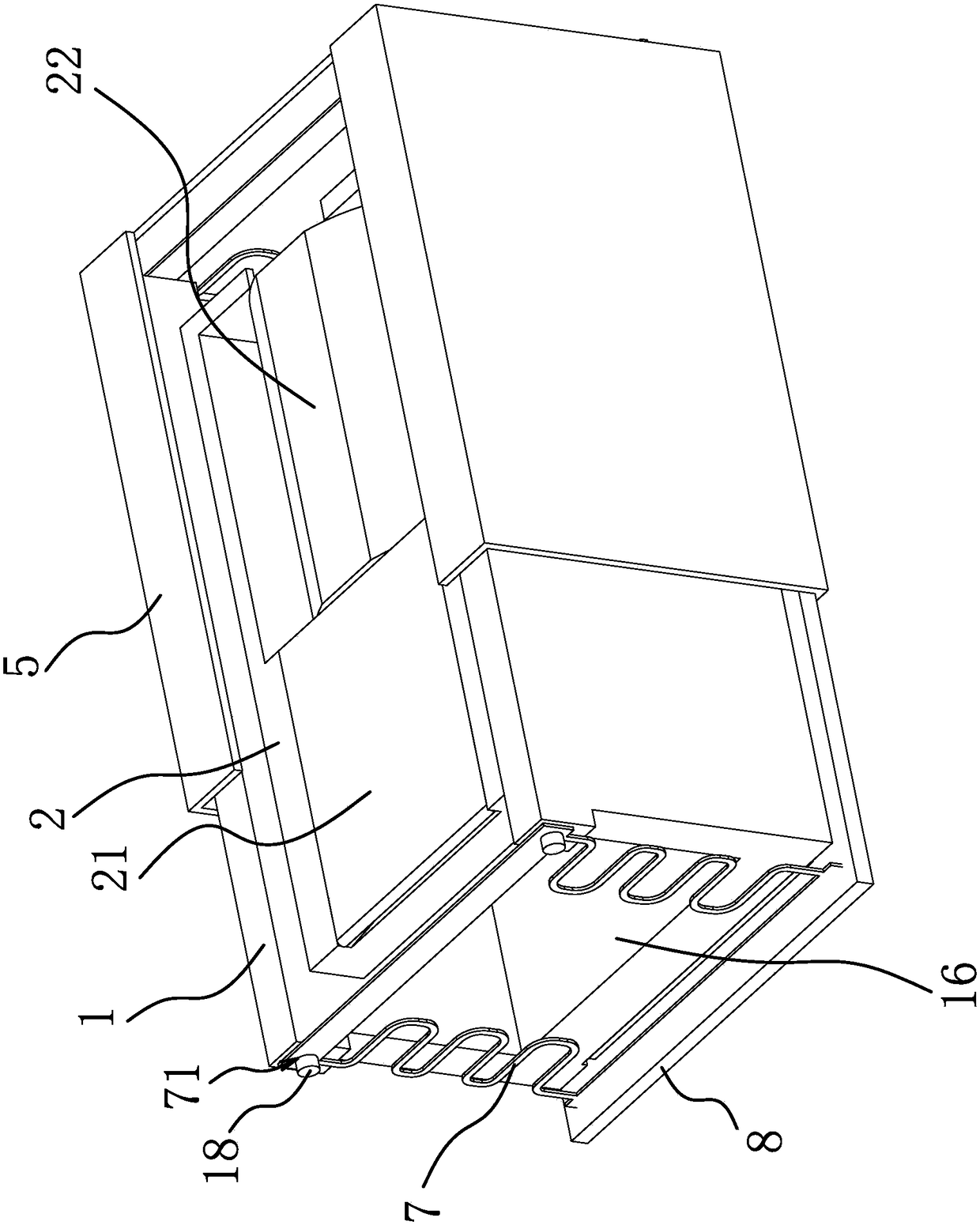
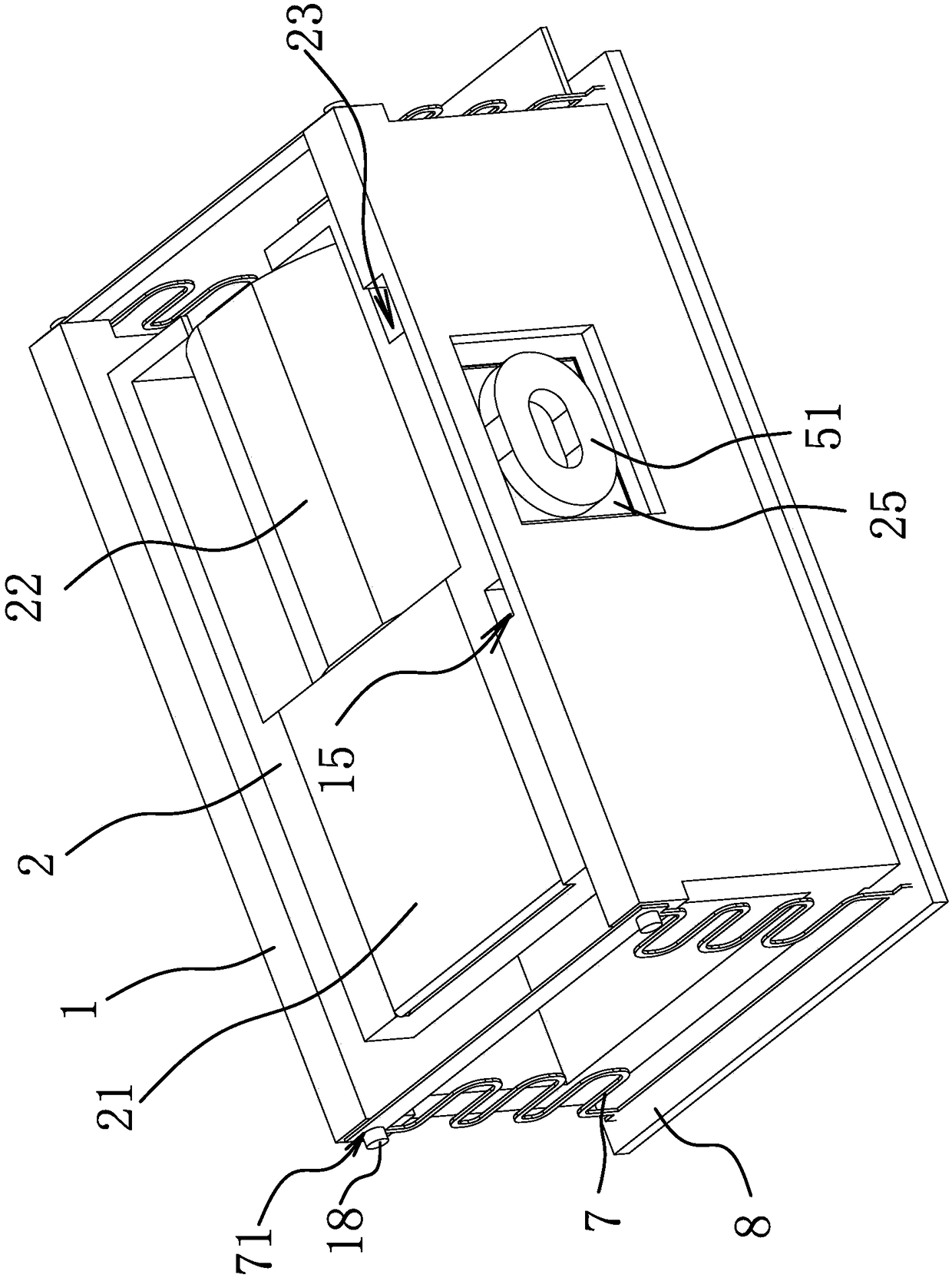
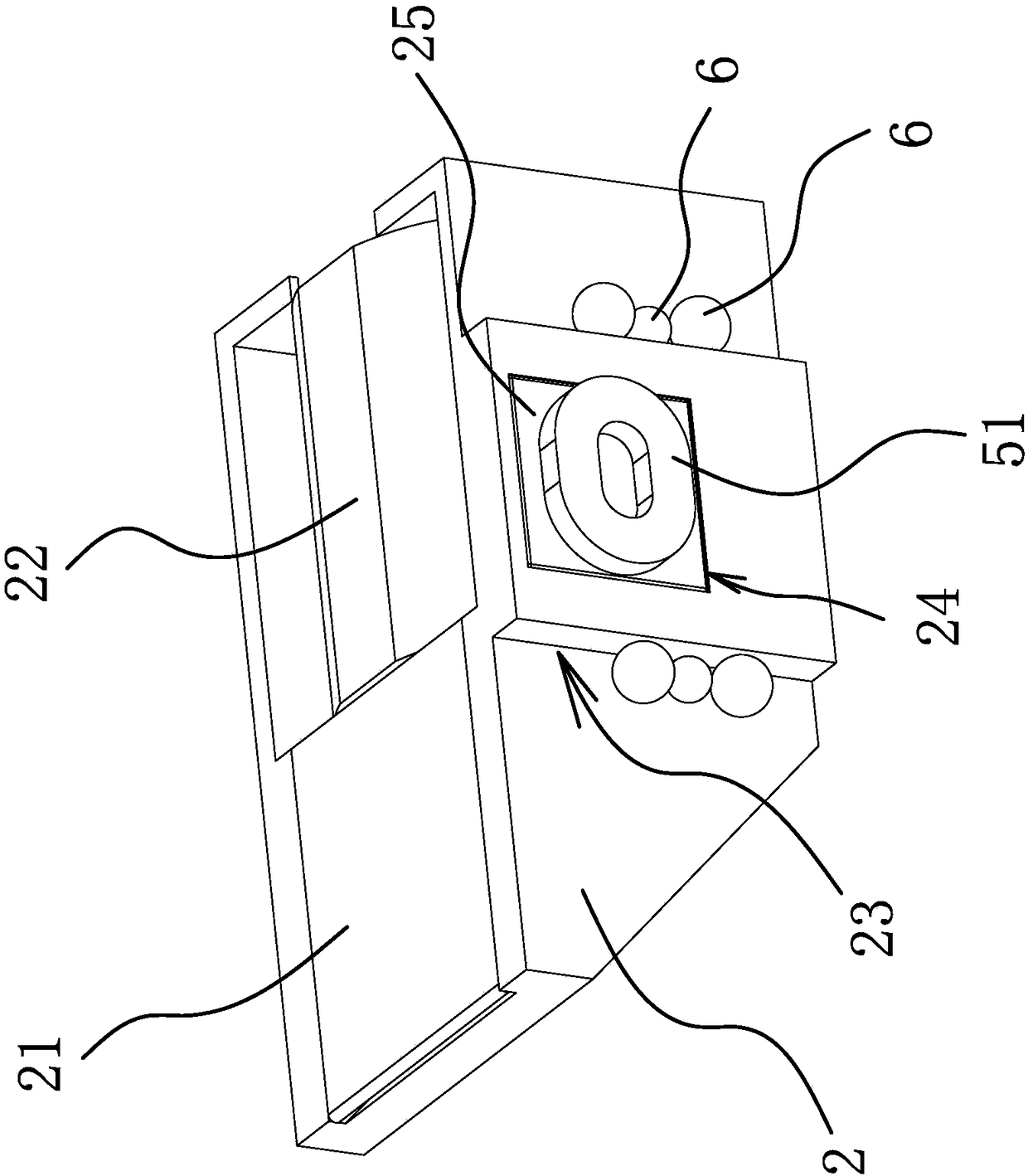
[0036] like figure 1 As shown in the image stabilization structure of the camera, the camera includes a frame and a limit frame 2 , the limit frame 2 is arranged in the frame, and the limit frame 2 is provided with a prism 21 and a lens 22 .

[0037] Specifically, as Figure 1-5 As shown, a focusing magnet 3 is arranged in the frame, a circuit board 4 is arranged in the frame, a focusing coil 41 is arranged on the circuit board 4, and the focusing coil 41 is arranged opposite to the focusing magnet 3, and an outer cover 5 is arranged on the upper frame of the frame. The structure includes an anti-shake coil 1 42 arranged on the circuit board 4 , an anti-shake coil 2 51 arranged on the outer cover 5 , an anti-shake magnet 1 11 arranged in the fr...


PUM


Abstract

The invention provides a camera anti-shake structure and belongs to the technical field of machinery. The structure solves the serious problem of shake of two axes of the existing camera. According tothe camera anti-shake structure, a camera comprises a framework and a limiting frame; the limiting frame is arranged in the framework; a prism and a lens are arranged in the limiting frame; a focusing magnet is arranged in the framework; an outer cover is arranged on the framework in a covering manner; the anti-shake structure comprises an anti-shake coil I arranged on a circuit board, an anti-shake coil II arranged on the outer cover, an anti-shake magnet I arranged in the framework and an anti-shake magnet II arranged on a side wall of the limiting frame; the anti-shake coil I and the anti-shake magnet I are arranged oppositely; the anti-shake coil II and the anti-shake magnet II are arranged oppositely; and length directions of the anti-shake coil I and the anti-shake coil II are perpendicular to a length direction of the focusing coil. The anti-shake magnet II and the anti-shake coil II of the structure can vertically compensate a deviation of camera shake in a shooting process ofa person, and the anti-shake adjustment of the two axes of the camera is achieved.

Description

technical field [0001] The invention belongs to the technical field of machinery, and relates to an anti-shake structure for a camera. Background technique [0002] The optical anti-shake camera module usually includes a housing, a lens unit, a focusing unit, an anti-shake unit and a shooting unit. The lens unit is accommodated in the focusing unit, the focusing unit is arranged above the anti-shake unit, and the focusing unit and the anti-shake unit pass through four It has an elastic suspension wire connection, so in the absence of shaking, the focusing unit can drive the lens unit to move along the optical axis relative to the shooting unit to capture a clear image, and in the case of shaking, the lens unit may be perpendicular to the optical axis. A slight movement occurs in the plane of the camera, and the anti-shake unit drives the focusing unit and the lens unit to make opposite displacements in the plane perpendicular to the optical axis to compensate for the amount ...

Claims


Application Information

Patent Timeline
Patent Type & Authority Applications(China)
IPC IPC(8): G02B27/64G03B5/00
CPCG02B27/646G03B5/00
Inventor 王先玉
Owner ZHEJIANG XINGXING TECH CO LTD
Learn More