Proportional batching device on extruding machine

An extruder and proportional technology, which is applied in the field of proportional batching devices, can solve problems such as the inability to achieve proportional batching.

Inactive Publication Date: 2018-07-27
魏缘意
View PDF1 Cites 0 Cited by
  • Summary
  • Abstract
  • Description
  • Claims
  • Application Information

AI Technical Summary

Problems solved by technology

But this kind of device can't realize proportionate batching

Method used


Image

  • Proportional batching device on extruding machine
  • Proportional batching device on extruding machine
  • Proportional batching device on extruding machine

Examples


Embodiment Construction

[0024] The following will clearly and completely describe the technical solutions in the embodiments of the present invention with reference to the accompanying drawings in the embodiments of the present invention. Obviously, the described embodiments are only some, not all, embodiments of the present invention. Based on the embodiments of the present invention, all other embodiments obtained by persons of ordinary skill in the art without making creative efforts belong to the protection scope of the present invention.

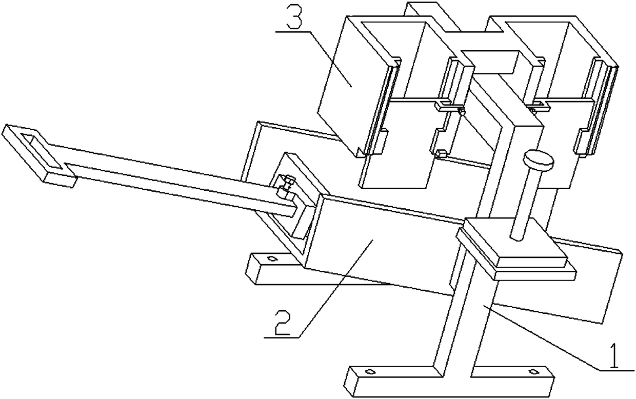
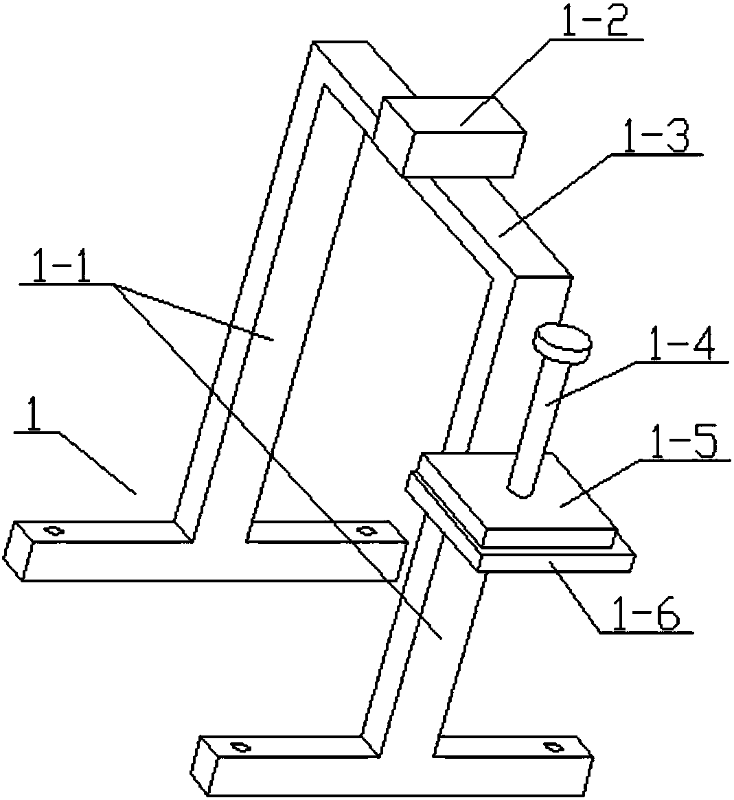
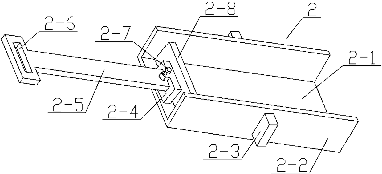
[0025] see Figure 1-6 , the invention provides a technical solution: a proportional batching device on an extruder, including a bracket assembly 1, a feed channel assembly 2 and a quantitative batching box 3, and the bracket assembly 1 includes a vertical bracket 1-1, a connecting block 1 -2, horizontal frame 1-3, hand bar 1-4, compacting plate 1-5 and placement plate 1-6, the middle position of the upper end of the horizontal frame 1-3 is connected with the ...


PUM


Abstract

The invention discloses a proportional batching device on an extruding machine. The proportional batching device comprises a bracket assembly, a feeding channel assembly and a quantitative batching box. The bracket assembly comprises a vertical bracket, a connecting block, a transverse frame, a hand rod, a compaction plate and a storing plate. The middle of the upper end of the transverse frame isconnected with the connecting block through a screw. The two ends of the transverse frame are fixedly connected with the vertical bracket. The vertical bracket at the front end is connected with thehorizontal storing plate through welding. The upper end of the compaction plate is fixedly connected with the hand rod. The compaction plate is stored at the upper end of the storing plate.

Description

technical field [0001] The invention relates to a batching device, in particular to a proportional batching device on an extruder. Background technique [0002] The application number is CN201520645264.2, a pressure-feeding device of a plastic extruder. The present invention is a pressure-feeding device of a plastic extruder, including a conveying shell, a hot-melt zone arranged on the upper left of the conveying shell, and a set The bearing on the right side of the conveying shell, the main motor set on the lower left of the conveying shell, the discharge port set on the lower right of the conveying shell, and the feet set under the conveying shell, the primary crushing zone is set above the hot melting zone area, and the feeding port above the primary crushing area, the inside of the conveying shell is provided with a rotating shaft, and the surface of the rotating shaft is provided with cutting teeth, and the inside of the hot melting area is provided with insulation cott...

Claims


Application Information

Patent Timeline
Patent Type & Authority Applications(China)
IPC IPC(8): B29C47/10B29C47/92B29C48/92
CPCB29C48/286B29C48/92B29C2948/92828
Inventor 魏缘意
Owner 魏缘意
Why Eureka
Try Eureka