Waste oil recycling monitoring system for motor vehicle

A monitoring system and motor vehicle technology, applied in the general control system, control/regulation system, transmission system, etc., can solve the problems of destroying enterprises, secondary pollution of facilities, backward production, collection, and classification processes, and achieve the goal of preventing leakage Effect

Inactive Publication Date: 2018-07-10
重庆鸿净环保科技开发有限公司
View PDF4 Cites 4 Cited by
  • Summary
  • Abstract
  • Description
  • Claims
  • Application Information

AI Technical Summary

Problems solved by technology

[0005] Problems existing in the control of hazardous waste pollution in my country: (1) The management, production, collection, and classification processes are backward, the equipment is simple, and the layout is scattered, resulting in a large amount of pollutants and serious pollution; facilities, and mainly dispose of the waste generated by itself, only a very small number of facilities provide some paid services to the outside world
Due to the lack of relevant technical standards and operating permit system, most facilities have the possibility of causing secondary pollution, and the environmental risk is very high
(2) Large discharge, secondary pollution or potential secondary pollution, outdated disposal facilities, unclear production situation, random collection, transportation and treatment, and damage to the dangerous outlet left by the enterprise
(3) The storage of waste cannot meet the requirements for storage of hazardous waste
Any failure to meet the requirements may cause irreparable harm to the environment
(4) Hazardous waste incineration units tend to be smaller and have little environmental control

Method used


Image

  • Waste oil recycling monitoring system for motor vehicle
  • Waste oil recycling monitoring system for motor vehicle
  • Waste oil recycling monitoring system for motor vehicle

Examples


Embodiment Construction

[0027] The preferred embodiments of the present invention will be described in detail below with reference to the accompanying drawings.

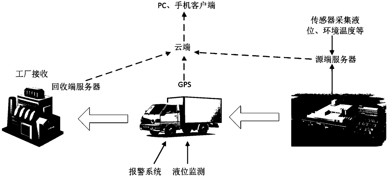
[0028] figure 1 is the frame diagram of the present invention, such as figure 1 As shown, the present invention is a vehicle waste oil recovery monitoring system, including a source server, a recovery server, a cloud and a client.

[0029] The source server is set at the production point of motor vehicle waste oil, such as each motor vehicle 4S shop, motor vehicle scrap processing point, etc., and the recycling end server is set at the motor vehicle waste oil processing point such as a special processing factory.

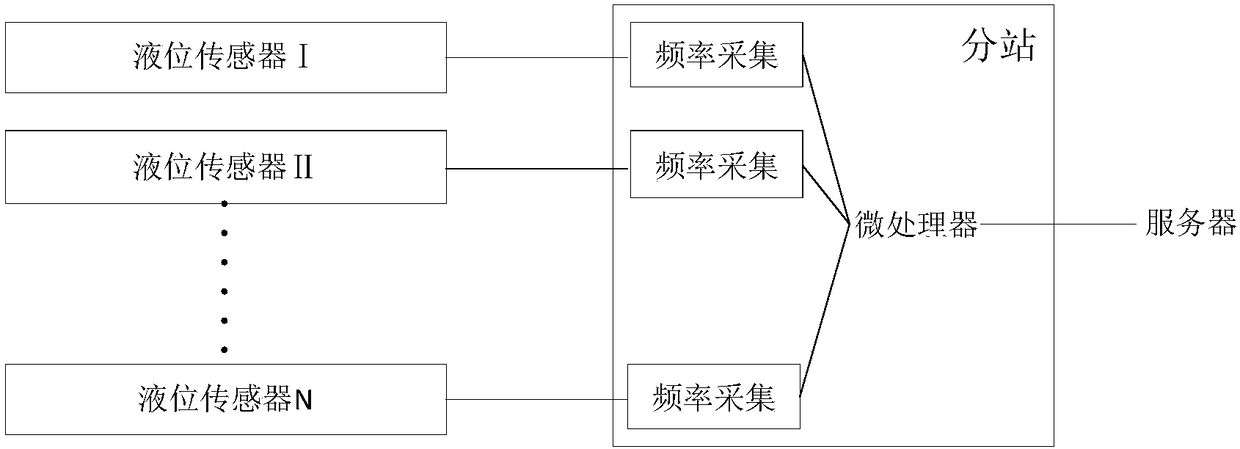
[0030] figure 2 It is a structural diagram of the source server of the present invention. The source server of the present invention is connected to a substation, and the substation includes a microprocessor and multiple groups of frequency acquisition units. The frequency acquisition units are all connected to the microproces...


PUM


Abstract

The invention relates to a waste oil recycling monitoring system for a motor vehicle, and the system comprises a source side server, a recycling side server, a cloud side, and a client. The source side server is disposed at a production site of motor vehicle waste oil, and the recycling side server is disposed at a processing site of the motor vehicle waste oil. The source side server is connectedto a branch station, and the branch station comprises a microprocessor and a plurality of groups of frequency collection units. Each frequency collection unit is connected to the microprocessor, andis also connected to a liquid level sensor. The liquid level sensor is disposed in a motor vehicle waste oil recycling box, and is used for detecting the liquid level of waste oil. The recycling end server is used for the statistical operation of the data of waste oil received by a receiving side and the processing data of waste oil, and transmitting the data to the cloud side. The cloud side receives the data transmitted by the source side server and the recycling side server. The client is used for the access to the data of the cloud side. The system is used for monitoring all links from theproduction and transportation to the processing of waste oil of the motor vehicle, and improves the processing efficiency of the waste oil of the motor vehicle.

Description

technical field [0001] The invention belongs to the technical field of hazardous waste treatment, and relates to a motor vehicle waste oil recovery monitoring system. Background technique [0002] Today, China's economy is developing rapidly, and the production scale of motor vehicles is huge, which is accompanied by aggravation of pollution problems. Faced with this situation, environmental protection measures should be taken quickly. This requires rapid development of environmental protection activities and investment in environmental protection in the near future. Because traditional management regulations and management systems do not put forward precise management requirements and management responsibilities are not clear, some special hazardous wastes are mixed with municipal solid waste and discharged together, which has aroused great concern in the society. Due to the long-term lack of scientific management systems and supporting treatment and disposal technologies...

Claims


Application Information

Patent Timeline
Patent Type & Authority Applications(China)
IPC IPC(8): G05B19/042H04L29/08H04N7/18
CPCH04L67/10H04L67/125H04N7/18G05B19/0423G05B2219/25257H04L67/52
Inventor 何德树何星锦何思颖
Owner 重庆鸿净环保科技开发有限公司
Why Eureka
Try Eureka