Annular sliding rail type steel structure 3D printing and processing platform

A 3D printing and processing platform technology, applied in processing platforms/substrates, additive processing, etc., can solve problems such as difficulty in ensuring accuracy and product quality, unstable connection between circular table tops and circular slide rails, etc., to facilitate processing operations, The effect of overcoming work fatigue and increasing the working radius

Inactive Publication Date: 2018-07-06
HKUST TIANGONG INTELLIGENT EQUIP TECH (TIANJIN) CO LTD
View PDF1 Cites 0 Cited by
  • Summary
  • Abstract
  • Description
  • Claims
  • Application Information

AI Technical Summary

Problems solved by technology

In order to improve the assembly efficiency of steel structures and speed up construction efficiency, the steel structure skeletons in the prior art are usually punched, bent and surface treated in the factory, and then directly transported to the construction site for assembly: but for some special steel structures Due to the requirement of high precision, the components need to be assembled and then transported as a whole. In the workshop of the prior art, there is usually no special equipment for this kind of operation, and they are usually assembled on the spot in the workshop, which makes it difficult to guarantee the accuracy and product quality. , in the prior art, for example, the invention patent with application number 201710599613.5 includes a circular slide rail and a clamping platform, the clamping platform includes a base, a circular table and a clamping mechanism, and the bottom of the base slides through an arc-shaped chute Installed on the ring-shaped slide rail, the circular table is set on the upper part of the base, and the center of the circular table is provided with a mounting hole. The clamping mechanism includes a mounting column, a mounting plate and two clamping arms. The clamping mechanism passes through The mounting column is rotatably installed in the mounting hole on the table. The upper surface of the mounting plate is provided with two parallel slides with a convex cross-section. The clamping arm passes through the slider at the bottom. Slidingly installed in the slideway, a return spring is set between the two clamped sliders, one of the clamping arms is provided with a horizontal slide bar, and the other clamping arm is provided with a slide hole matched with the horizontal slide bar , the movable end of the horizontal slide rod is provided with an external thread and a nut matched with it. Although the invention is simple in structure, there are many deficiencies and defects. In the existing equipment, there are defects in the design of the circular table top. The connection of the slide rail is unstable, and the spring and the clamping slider. When an object is placed on the circular table, the heavy object will drive the spring down and press the circular slide rail to increase the resistance of the slider, and the sliding is not smooth. For these situations , in order to avoid the above-mentioned technical problems, it is indeed necessary to provide an annular slide rail type steel structure 3D printing processing platform to overcome the defects in the prior art

Method used


Image

  • Annular sliding rail type steel structure 3D printing and processing platform
  • Annular sliding rail type steel structure 3D printing and processing platform
  • Annular sliding rail type steel structure 3D printing and processing platform

Examples


Embodiment Construction

[0023] The following will clearly and completely describe the technical solutions in the embodiments of the present invention with reference to the accompanying drawings in the embodiments of the present invention. Obviously, the described embodiments are only some, not all, embodiments of the present invention. Based on the embodiments of the present invention, all other embodiments obtained by persons of ordinary skill in the art without making creative efforts belong to the protection scope of the present invention.

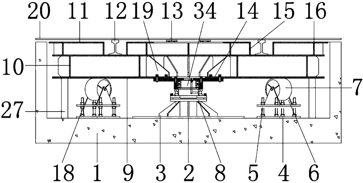
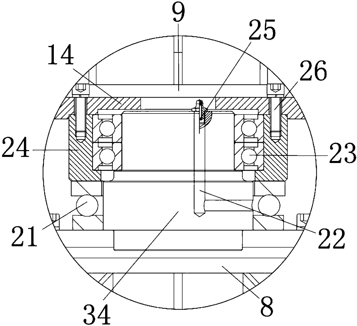
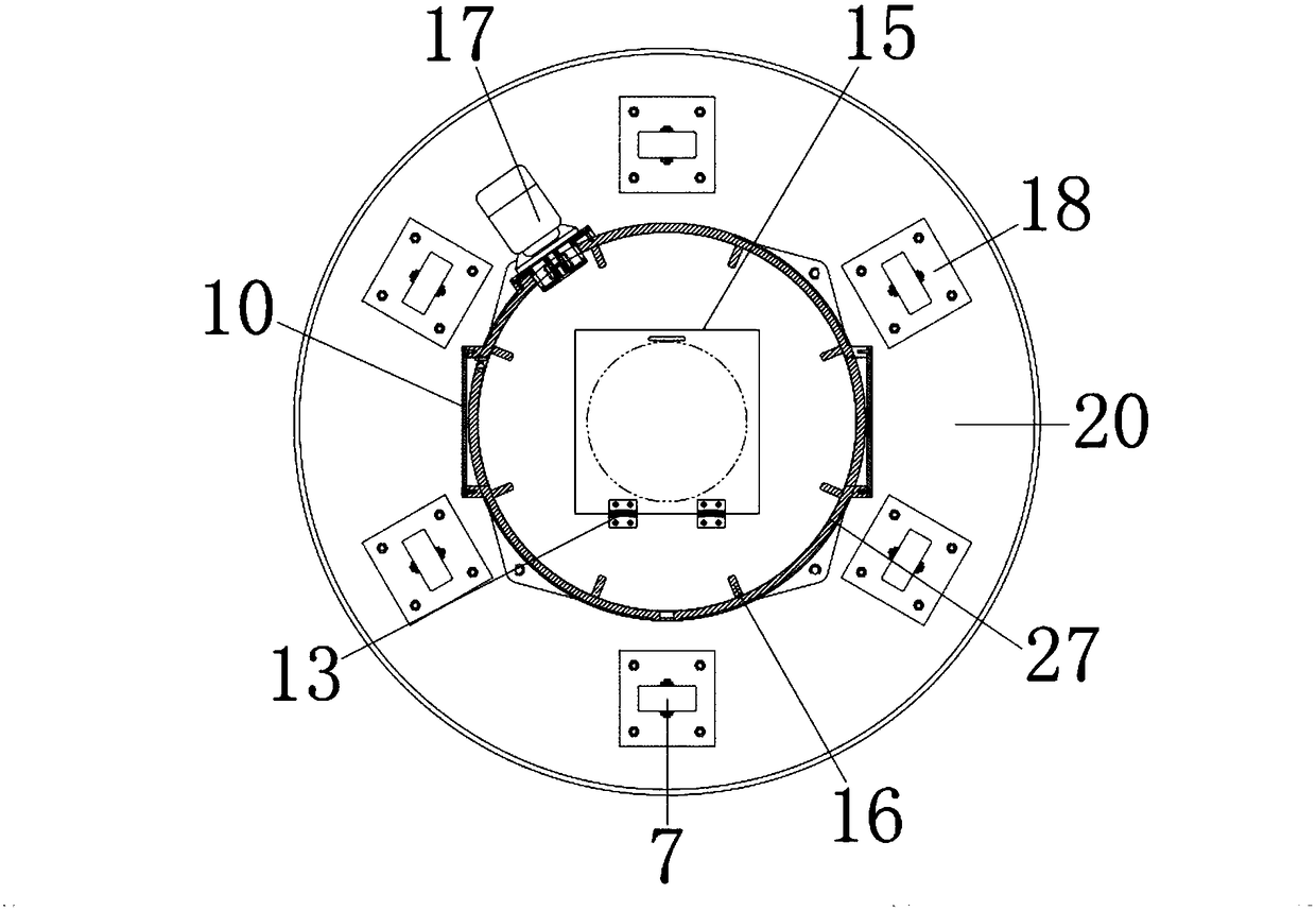
[0024] see Figure 1-4, the present invention provides a technical solution: a ring-shaped rail-type steel structure 3D printing processing platform, including a body 1, the body 1 is made of stainless steel, and is used to install various internal parts, the inner wall of the body 1 is installed with a base 2, and the base 2 It is made of stainless steel and is used to install and fix the rotating shaft 34. The lower surface of the base 2 is connected to the ...


PUM


Abstract

The invention discloses an annular sliding rail type steel structure 3D printing and processing platform. The annular sliding rail type steel structure 3D printing and processing platform comprises amachine body. A seat is installed on the inner wall of the machine body, and the lower surface of the seat is connected with the upper surface of the machine body; a rotating shaft is installed on theupper surface of the seat, and the lower surface of the rotating shaft is connected with the upper surface of the seat; and a plane buried plate is installed on the upper surface of the machine body,and the upper surface of the plane buried plate is connected with the lower surface of the machine body. According to the annular sliding rail type steel structure 3D printing and processing platform, through the coordination between the machine body and a top plate, under the action of the rotating shaft, the rotating shaft is driven by a motor to rotate to drive the top plate to rotate, so thatprocessing parts placed on the top plate can be adjusted by any angles to facilitate the processing operation of an operator; operation steps are simplified, the operation difficulty of work is reduced, the placing requirement of the processing parts is met, the processing angle of the processing parts is adjusted, and at the same time, the working radius is increased, so that more processing parts can be placed, and the working efficiency is improved.

Description

technical field [0001] The invention relates to the technical field of steel structure processing, in particular to an annular slide rail type steel structure 3D printing processing platform. Background technique [0002] Steel structure is a basic component made of section steel or steel plate. According to the requirements of use, it is a load-bearing mechanism composed of welding or bolt connection according to certain rules. Steel structure is widely used in various engineering constructions, such as steel bridges. , steel workshops, steel gates, various large pipeline containers, high-rise buildings and tower rail mechanisms, etc., due to the steel structure system has comprehensive advantages such as light weight, easy installation, short construction period, good seismic performance, fast investment recovery, and less environmental pollution. , has been widely adopted in the construction industry. In order to improve the assembly efficiency of steel structures and sp...

Claims


Application Information

Patent Timeline
Patent Type & Authority Applications(China)
IPC IPC(8): B29C64/245B33Y30/00
CPCB33Y30/00
Inventor 张超钱浩马向军程锦泽吕胜雨王鹏翔
Owner HKUST TIANGONG INTELLIGENT EQUIP TECH (TIANJIN) CO LTD
Why Eureka
Try Eureka