Automatic power-on and power-off power supply socket

A power supply socket and automatic technology, applied in the field of electric power, can solve the problems of burning electrical equipment, unstable power supply connection, plug disconnection and connection, etc., so as to increase the safety performance of use and reduce accidental electric shock accidents of children

Inactive Publication Date: 2018-06-29
中山市新发装饰工程有限公司
View PDF5 Cites 1 Cited by
  • Summary
  • Abstract
  • Description
  • Claims
  • Application Information

AI Technical Summary

Problems solved by technology

[0002] At present, the power supply of electrical equipment is mainly to insert the plug directly into the socket to connect to the power supply. However, the power supply socket will always be in the power supply state. If there are children in the family who directly insert the conductive metal rod into the power supply hole, it will cause electric shock. Accidents, there are great safety hazards, and the existing plugs are inserted into the sockets in the form of clamping. Although this clamping form is more convenient to operate, the length of the wires between the plug and the electrical equipment is different. Yes, and after the plug is inserted into the socket, there is no other locking member in the socket to lock the plug. Therefore, when the electric wire is accidentally kicked and hit by mistake, the plug will be separated from the matching connection with the socket, resulting in failure of the electrical equipment. Sudden power failure will cause burning of electrical equipment, so there is a potential safety hazard of unstable power supply connection in the existing matching connection between the plug and the socket

Method used


Image

  • Automatic power-on and power-off power supply socket
  • Automatic power-on and power-off power supply socket
  • Automatic power-on and power-off power supply socket

Examples


Embodiment Construction

[0023] The preferred embodiments of the present invention will be described in detail below in conjunction with the accompanying drawings, so that the advantages and features of the present invention can be more easily understood by those skilled in the art, so as to define the protection scope of the present invention more clearly.

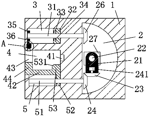
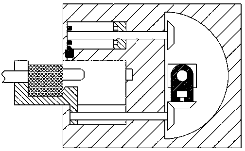
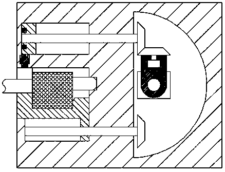
[0024] refer to Figure 1-7A power supply socket that can be automatically powered on and off is shown, including a socket body 1, a slot 4 is provided on the left end surface of the socket body 1, and a power supply hole 41 is provided on the right end wall of the slot 4. The bottom end wall of the slot 4 is provided with a first slide slot 5 communicating with the slot 11, and a second slide slot 3 is arranged above the slot 4 in the socket body 1, and in the socket body 1 The right end of described slot 4 is provided with rotating groove 2, and described rotating groove 2 is provided with rotating drive assembly, and described slot 4 is provid...


PUM


Abstract

The invention discloses an automatic power-on and power-off power supply socket comprising a socket body. The left end surface of the socket body is provided with an inserting slot. The right end wallof the inserting slot is provided with a power supply hole. The bottom end wall of the inserting slot is provided with a first slide slot which is communicated with the inserting slot. The socket body is provided with a second slide slot above the inserting slot. The socket body is provided with a rotating slot on the right end of the inserting slot. The rotating slot is provided whit a rotatingdriving component. The inserting slot is provided with a slide frame in a left-and-right sliding way. The structure is simple, the production cost is low and power supply is safe and stable so that the accident of electric shock in the present life can be effectively eliminated, the life safety of children can be guaranteed, automatic power-on and power-off of the power connector and the power supply hole can be realized, the situation that the power connector of the plug is separated from the power supply hole because of mistakenly hitting and colliding the electric wire can be avoided and the use requirements of the power utilization equipment can be met.

Description

technical field [0001] The invention relates to the field of electric power, in particular to a power supply socket capable of automatically connecting and disconnecting power. Background technique [0002] At present, the power supply of electrical equipment is mainly to insert the plug directly into the socket to connect to the power supply. However, the power supply socket will always be in the power supply state. If there are children in the family who directly insert the conductive metal rod into the power supply hole, it will cause electric shock. Accidents, there are great safety hazards, and the existing plugs are inserted into the sockets in the form of clamping. Although this clamping form is more convenient to operate, the length of the wires between the plug and the electrical equipment is different. Yes, and after the plug is inserted into the socket, there is no other locking member in the socket to lock the plug. Therefore, when the electric wire is accidental...

Claims


Application Information

Patent Timeline
Patent Type & Authority Applications(China)
IPC IPC(8): H01R13/44H01R13/71H01R13/627
CPCH01R13/44H01R13/6278H01R13/71
Inventor 虞海杰
Owner 中山市新发装饰工程有限公司
Why Eureka
Try Eureka