A scale-adjustable two-way synchronous compression experiment in-situ observation device

A two-way synchronization and observation device technology, which is applied to measuring devices, using stable tension/pressure to test the strength of materials, instruments, etc., can solve problems such as errors, less equipment, and incomplete theoretical results, so as to ensure accuracy and rationality. The effect of reducing experiment cost and simple structure

Active Publication Date: 2020-09-15
CHONGQING UNIV
View PDF20 Cites 0 Cited by
  • Summary
  • Abstract
  • Description
  • Claims
  • Application Information

AI Technical Summary

Problems solved by technology

At present, there is still a lack of equipment that can study the deformation capacity and deformation behavior of materials under biaxial compression
In addition, only through the comparison of microstructure changes before deformation and after final deformation, omitting the study of the intermediate process is likely to lead to incomplete theoretical results or completely wrong results
At present, there are few in-situ experiments that can study the continuous change process of materials in a specific area during bidirectional compression, and there are even fewer equipments that can perform variable-scale loading in-situ electron microscope observation and tissue orientation determination of the microstructure in the deformed area.

Method used


Image

  • A scale-adjustable two-way synchronous compression experiment in-situ observation device
  • A scale-adjustable two-way synchronous compression experiment in-situ observation device
  • A scale-adjustable two-way synchronous compression experiment in-situ observation device

Examples


Embodiment Construction

[0018] The present invention will be described in detail below in conjunction with the accompanying drawings.

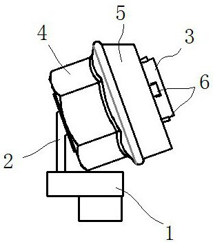
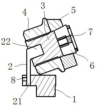
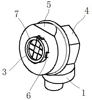
[0019] see Figure 1 to Figure 4 , the scale-adjustable two-way synchronous compression experiment in situ observation device includes a base 1 , a support column 2 , a screw 2 , a loading nut 4 , a pressure ring 5 and a wedge 6 . The screw 3 is fixed above the base 1 through the support column 2, and it is composed of a lower threaded part 31 and an upper loading part 32. The threaded part 31 is threadedly matched with the loading nut 4, and the top of the loading part 32 is provided with a The groove 321 of the sample is evenly provided with accommodating groove 322 corresponding to the wedge block 6 along the circumferential direction on the side wall of the loading part 32, and the upper part of the groove bottom of the accommodating groove 322 penetrates through the lower part of the side wall of the groove 321 , the shape of the wedge-shaped block 6 is large a...


PUM


Abstract

The invention discloses a ratio adjustable in-situ observation device for a bidirectional synchronization compression experiment. The device comprises a base, a support column, a screw, a loading nut,a press ring, and a wedge block. The screw is fixed above the base through the support column and is composed of an upper threaded part and a lower loading part. The threaded part cooperates with theloading part through threads. The top of the loading part is provided with a groove for placing a sample. An accommodation groove that cooperates with the wedge block is uniformly arranged in the lateral wall of the loading part along the circumferential direction. The upper part of the bottom of the accommodation groove is communicated with the lower part of the lateral wall of the groove. The wedge block is in a big end up shape. The upper part of the vertical surface is provided with an embossment. The embossment penetrates a channel and contacts with the sample. The inclined surface protrudes from the lateral surface of the screw. The lower end face of the press ring abuts on the upper end face of the loading nut. The inner side of the press ring slidingly cooperates with the inclinedsurface of the wedge block. The structure is simple, the loading state during the experiment process can be maintained, and the microscopic tissue change of a sample during the process of a compression test can be in-situ observed.

Description

technical field [0001] The invention relates to the field of material physical property testing, in particular to an in-situ observation device for bidirectional synchronous compression experiments with adjustable ratio. Background technique [0002] The use of high-strength forming materials has increased greatly in recent years, such as sheet metal and forgings. In order to improve the processing and production efficiency of metal materials and save production costs, it is necessary to conduct in-depth and detailed research on the microstructure evolution process of metal materials during the forming process. In the process of drawing, die forging, etc., if one of the three principal stresses is much smaller than the other two principal stresses, the minimum principal stress is approximately zero, and the metal material is often in a state of bidirectional compressive stress, which is different from uniaxial tension. Or the uniaxial stress state during compression, the bia...

Claims


Application Information

Patent Timeline
Patent Type & Authority Patents(China)
IPC IPC(8): G01N3/08G01N3/02G01N3/06G01N23/2251
CPCG01N3/02G01N3/06G01N3/08G01N23/22G01N2203/0019G01N2203/0641
Inventor 黄光胜夏大彪谢誉璐刘帅帅潘复生
Owner CHONGQING UNIV
Why Eureka
Try Eureka