A button-feeding device with a swing arm manipulator controlled by software

A technology of software control and manipulator, which is applied in the direction of storage device, feeding device, positioning device, etc., can solve the problems of poor versatility, reduce the trouble of customization and replacement, and achieve the effect of universality

Active Publication Date: 2019-06-07
上海在道科技有限公司
View PDF1 Cites 0 Cited by
  • Summary
  • Abstract
  • Description
  • Claims
  • Application Information

AI Technical Summary

Problems solved by technology

[0003] In order to overcome the disadvantages of poor versatility in the prior art, the present invention provides a button-feeding device with a swing arm manipulator controlled by software. The software controls the rotation of the stepping motor to drive the manipulator to complete receiving, gripping, swinging the arm and sending the buttons. The action of entering the punching die is completed by imitating the manual feeding method, which avoids the design of the push button track and push rod, thereby expanding the scope of application

Method used


Image

  • A button-feeding device with a swing arm manipulator controlled by software
  • A button-feeding device with a swing arm manipulator controlled by software
  • A button-feeding device with a swing arm manipulator controlled by software

Examples


Embodiment 1

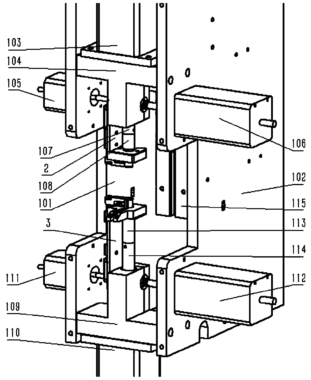
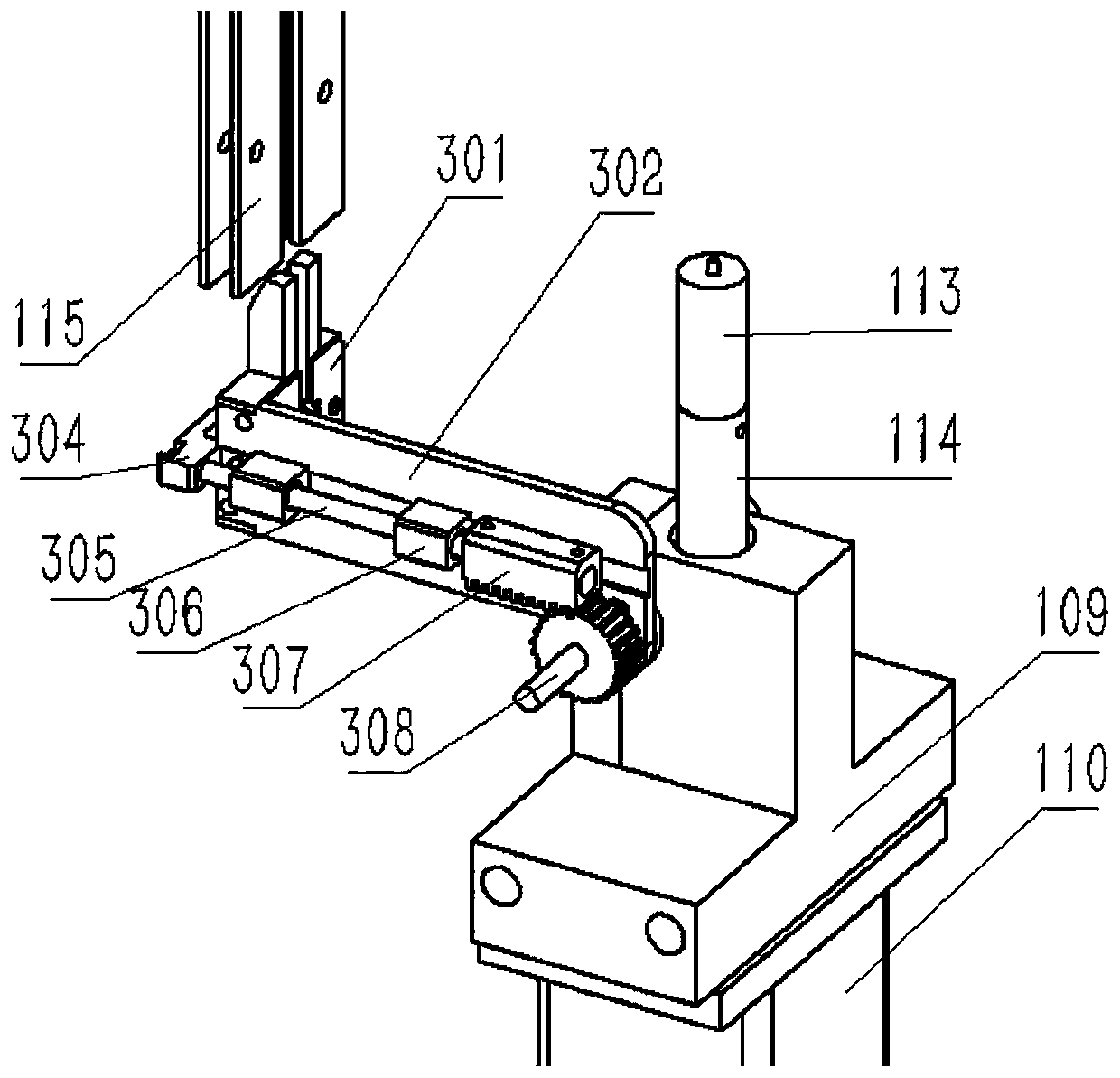
[0019] A button-feeding device with a swing arm manipulator controlled by software, used for button-down, see figure 1 , including a software control device, a left wallboard 101 and a right wallboard 102 opposite to it, a stamping seat 109 is fixed between the left and right wallboards, and a vertical through hole and a transverse through hole are arranged in the stamping seat 109, A bearing is arranged in the horizontal through hole, and a sliding sleeve is housed in the vertical hole. The punch rod 114 vertically passes through the stamping seat 109 through the sliding sleeve. Its swing shaft 303 is installed on the bearing in the transverse through hole of the stamping seat 109, on the left side of the swing arm manipulator 3, the button motor 111 is relatively connected with the gear 308 axis of the swing arm manipulator 3 and fixed on the left wallboard. On the left side, on the right side of the swing arm manipulator 3, the swing arm motor 112 is relatively connected wi...

Embodiment 2

[0024] This device can also adjust the direction and direction of the swing arm, the shape of the swing head, and change the installation direction to apply to dies with different orientations. For example, see figure 1, when installed upside down 180 degrees, the upper swing arm manipulator 2 can be used for buckle-up, and shares a software control with the lower swing arm manipulator 3 to form a buckle feeding system that works up and down simultaneously, including the left wall plate 101 and its opposite setting The right wallboard 102, the upper stamping seat 104 is fixed directly above the stamping seat 109 between the left and right wallboards, the upper stamping seat 104 is provided with a vertical through hole and a horizontal through hole, and the horizontal through hole is provided with Bearing, sliding sleeve is housed in the vertical hole, upper punch 107 passes through upper stamping seat 104 vertically through sliding sleeve, upper die 108 is installed on the lowe...

Embodiment 3

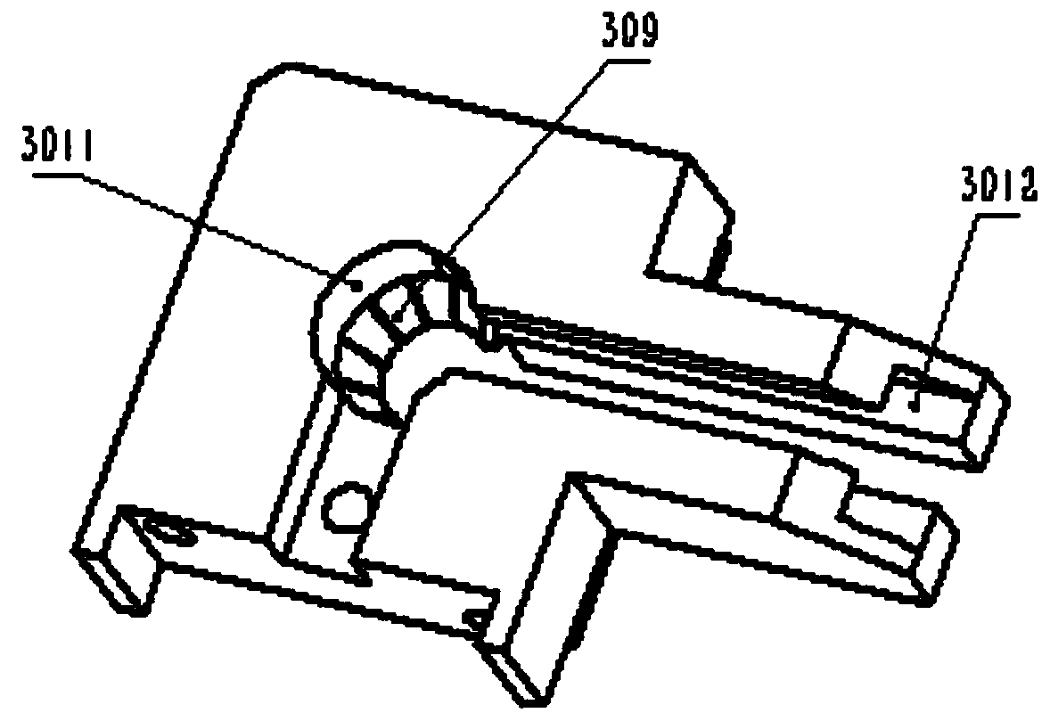
[0029] Design changes the round holes of the upper swing head 201 and the swing head 301 to be square holes, triangular holes, oval holes, polygonal holes and just be applicable to the feeding of more shaped nails, buttons, or similar materials.


PUM


Abstract

The invention discloses a swing arm mechanical arm buckle conveying device controlled by software. The swing arm mechanical arm buckle conveying device comprises a software control device, a left wallplate and a right wall plate opposite to the left wall plate. A punching base is fixed between the left wall plate and the right wall plate. A punching rod vertically penetrates the punching base through a sliding sleeve. A punching die is arranged at one end of the punching rod, and the other end of the punching rod is connected with a power mechanism. A swing arm mechanical arm is arranged on the punching base through a swing shaft of the swing arm mechanical arm. A buckle pressing motor and the axis of a gear of the swing arm mechanical arm are oppositely connected. The swing arm motor andthe axis of the swing shaft of the swing arm mechanical arm are oppositely connected. The swing arm mechanical arm comprises a swing arm, a swing head is arranged at one end of the swing arm, the swing shaft is connected to the other end of the swing arm, the swing shaft is arranged on a bearing of the punching base, and the sliding sleeve is arranged on the outer side face of the swing arm; a pressing rod penetrates the sliding sleeve, a pressing head is arranged at one end of the pressing rod, a rack is arranged at the other end of the pressing rod, and the gear is arranged to be matched with the rack and is coaxial to the swing shaft.

Description

technical field [0001] The invention relates to a feeding device of a swing arm manipulator controlled by software, especially a kind of clothing, shoes and hats, belts, luggage production, snap buttons, five-claw buttons, I-shaped buttons, large white buttons, rivets, and air holes. The automatic buckle feeding device. Background technique [0002] Clothing, shoes, hats, belts, and luggage factories frequently alternately use six types of fasteners: snap buttons, five-claw buttons, I-shaped buttons, large white buttons, rivets, and air eyes, and each type of button has different sizes. The working method of the existing automatic button feeding and sewing machine is that the front and back sides of the buttons are identified by the previous preparation process and the buttons are arranged in the first sliding button track, and then the push rod of the button feeding device moves along the second sliding button. The track pushes the button into the die and the button clip t...

Claims


Application Information

Patent Timeline
Patent Type & Authority Patents(China)
IPC IPC(8): B21D39/00B21D43/10
CPCB21D39/00B21D43/105
Inventor 李玉锋
Owner 上海在道科技有限公司
Why Eureka
Try Eureka