
Fan control method and device

A fan control and fan technology, applied in the electronic field, can solve the problem of low temperature adjustment efficiency, and achieve the effects of preventing further temperature rise, improving efficiency, and reducing delay

Active Publication Date: 2018-06-22
QINGDAO HISENSE MEDICAL EQUIP
View PDF6 Cites 21 Cited by
  • Summary
  • Abstract
  • Description
  • Claims
  • Application Information

AI Technical Summary

Problems solved by technology

[0005] Embodiments of the present invention provide a fan control method and device, which can solve the problem of low efficiency of temperature adjustment in related technologies

Method used


Image

  • Fan control method and device
  • Fan control method and device
  • Fan control method and device

Examples


Embodiment Construction

[0025] In order to make the object, technical solution and advantages of the present invention clearer, the embodiments of the present invention will be further described in detail below in conjunction with the accompanying drawings.

[0026] An embodiment of the present invention provides a fan control method, such as figure 1 As shown, the method may include:

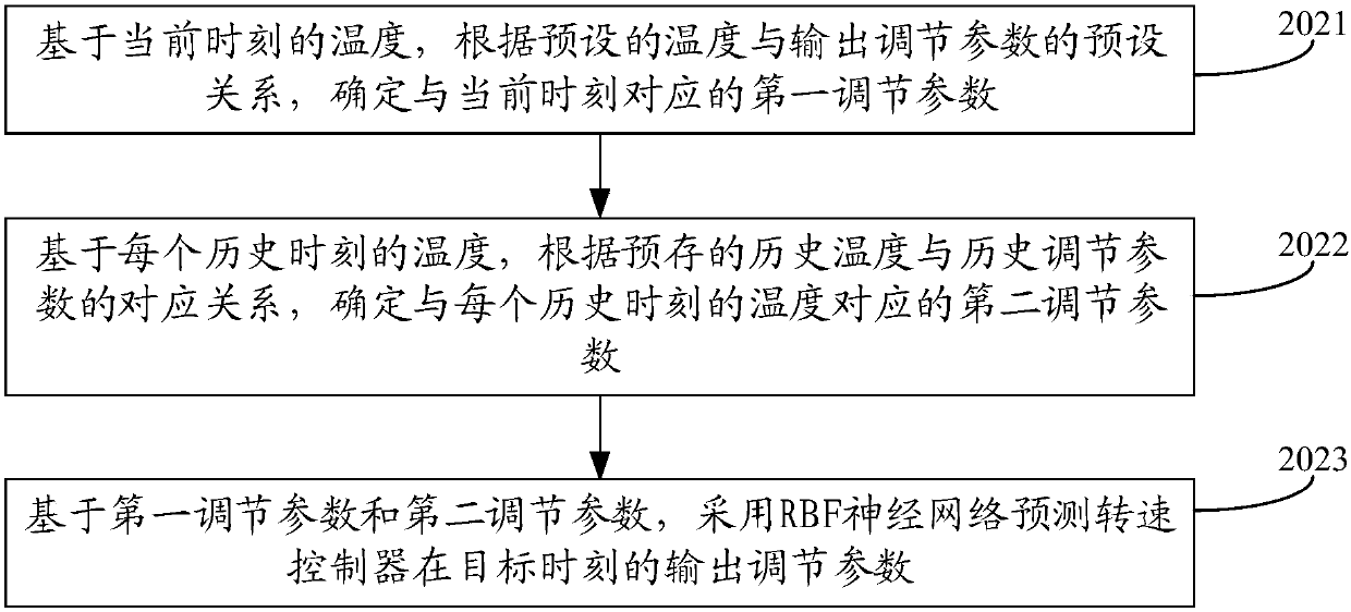
[0027] Step 101. According to the temperature at the current moment and the temperatures at multiple historical moments, the radial basis function RBF neural network is used to predict the output adjustment parameters of the speed controller at the target moment.

[0028] Wherein, the rotational speed controller is used to adjust the rotational speed of the fan, and the target time is a time after the current time.

[0029] It should be noted that the fan in the embodiment of the present invention can be a smart fan, the smart fan is provided with a temperature sensor, the temperature sensor can be used to collect th...


PUM


Abstract

The invention discloses a fan control method and device, and belongs to the technical field of electronic engineering. The method comprises the steps that according to current temperature and temperature at many historical times, output adjustment parameters of a rotary speed controller at target time are predicted by adopting a radial basis function RBF neural network, the rotary speed controlleris used for adjusting revolving speed of the fan, and the target time is the time after the current time; and at the target time, according to the output adjustment parameters, the output of controlsignals of the fan is modulated through the speed controller to adjust the speed of the fan. The fan control method and device effectively reduces time delay between the temperature and fan revolvingspeed control and improves the efficiency of temperature adjustment. The fan control method and device is used for cooling a chassis.

Description

technical field [0001] The invention relates to the field of electronic technology, in particular to a fan control method and device. Background technique [0002] With the development of multimedia technology, the integration density of video capture card, video output card and video stream control card in the multimedia chassis is getting higher and higher, which makes the heat inside the chassis locally concentrated, and then puts forward more and more requirements for the heat dissipation inside the chassis. high demands. [0003] In related technologies, a smart fan with a temperature sensor is generally used to dissipate heat from the chassis. The heat dissipation method is as follows: use the temperature sensor to detect the temperature in the chassis, and then control the speed of the smart fan according to the detected temperature. For example, when it detects When the temperature in the chassis is higher than the preset temperature range, the fan speed is correspo...

Claims


Application Information

Patent Timeline
Patent Type & Authority Applications(China)
IPC IPC(8): F04D27/00
Inventor 黄正发王靖武毛洪波
Owner QINGDAO HISENSE MEDICAL EQUIP
Learn More