
Valve assembly for injection valve, injection valve and method of assembling injection valve

A technology of valve components and injection valves, which is applied in the direction of fuel injection devices, special fuel injection devices, charging systems, etc., can solve the problems of increasing the length of the injector, and achieve the effect of reducing the overall length and simple assembly

Active Publication Date: 2021-08-03
VTESCO TECH GMBH
View PDF7 Cites 0 Cited by
  • Summary
  • Abstract
  • Description
  • Claims
  • Application Information

AI Technical Summary

Problems solved by technology

However, this increases the length of the injector

Method used


Image

  • Valve assembly for injection valve, injection valve and method of assembling injection valve
  • Valve assembly for injection valve, injection valve and method of assembling injection valve
  • Valve assembly for injection valve, injection valve and method of assembling injection valve

Examples


Embodiment Construction

[0031] Elements of the same design and function that appear in different figures are designated with the same reference numerals.

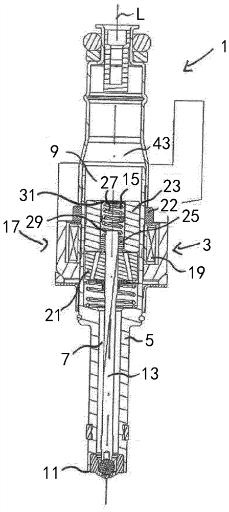
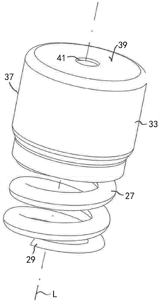
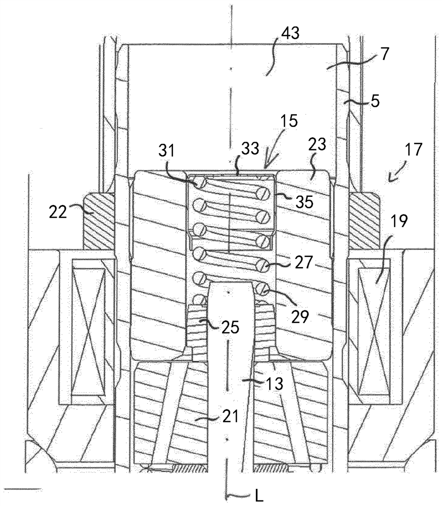
[0032] figure 1 A fluid injection valve 1 according to an exemplary embodiment is shown in a schematic longitudinal section. figure 1 The details are in figure 2 Shown enlarged.

[0033] exist figure 1 and figure 2 The fluid injection valve 1 shown in is particularly suitable for metering fuel in internal combustion engines. However, the invention can also be used in other types of injection valves.

[0034] Injection valve 1 includes a valve assembly 3 . The valve assembly 3 comprises a valve body 5 having a central longitudinal axis L. As shown in FIG. The valve body 5 includes a cavity 7 . The chamber 7 has a fluid outlet portion 11 . The fluid outlet portion 11 is in hydraulic communication with the fluid inlet portion 9 of the chamber 7 via the chamber 7 . In particular, the fluid inlet portion 9 and the fluid outlet portion 11 ar...


PUM


Abstract

The valve assembly (3) comprises a valve body (5) having a cavity (7) and a valve needle (13) axially movable within said cavity (7). The valve needle (3) also comprises a preloaded calibration spring (15) for biasing said valve needle (13), said calibration spring (15) comprising an axially compliant spring element (27), said spring element (27) has a lower part (29) assigned near one end of said valve needle (13) and an upper part (31) assigned a distance from said valve needle (13) a distance in which the calibration spring (15) is preloaded by press-fitting a fixing area (35) of the calibration spring (15) with a fixing element of the valve assembly (3), wherein the fixing area (35 ) extend laterally around the upper portion (31 ) of the spring element (27) and / or downwardly from the upper portion (31 ) of the spring element (27) towards the lower portion (29).

Description

technical field [0001] The present invention relates to valve assemblies for fluid injection valves and fluid injection valves. Furthermore, the invention also relates to a method for assembling a fluid injection valve. Background technique [0002] A valve assembly for a fluid injection valve includes a valve body including a cavity having a fluid inlet portion and a fluid outlet portion; and a valve needle axially movable within the cavity. The valve needle prevents fluid flow through the fluid outlet portion in the closed position and releases fluid flow through the fluid outlet portion in the other position. The valve needle can be actuated by an electromagnetic actuator unit. [0003] The valve needle is biased towards the closed position by a preloaded calibration spring. The calibration spring may be preloaded by press fitting the filter tube or fuel tube into the housing, pole piece or another element of the injection valve disclosed in US 6,997,404 B2. A filter ...

Claims


Application Information

Patent Timeline
Patent Type & Authority Patents(China)
IPC IPC(8): F02M61/16F02M61/20
CPCF02M61/168F02M61/20F02M2200/50F02M2200/8061F02M2200/505F02M61/10F02M61/205
Inventor C.哈曼M.佐里亚尼
Owner VTESCO TECH GMBH
Learn More