Charging device, charging equipment and charging control method
A charging device and charging electrode technology, which is applied in the direction of circuit devices, battery circuit devices, current collectors, etc., can solve the problems of high requirements for terminal placement, cumbersome charging for users, and poor user experience, so as to improve charging experience and flexible charging methods Effect
- Summary
- Abstract
- Description
- Claims
- Application Information
AI Technical Summary
Problems solved by technology
Method used
Image
Examples
Embodiment 1
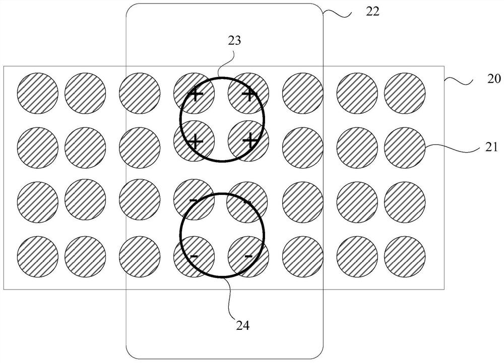
[0039] figure 1 It is a schematic structural diagram of a charging device provided in Embodiment 1 of the present invention. The charging device of this embodiment can be applied to charging equipment for charging. The device can be implemented in the form of software and / or hardware, and the device specifically includes:
[0040] The detection unit 11, the control unit 12 and the contact pins 13 arranged according to the preset rules, wherein the detection unit 11 is used to detect the preset characteristics of the charging electrodes arranged on the charging equipment; the charging electrodes include A first charge electrode with a magnetic region and a second charge electrode with a magnetic region, the magnetic region of the first charge electrode having an opposite magnetic pole to the magnetic region of the second charge electrode. The control unit 12 is connected with the detection unit, and is used to control the positive and negative polarities of the contact pins i...
Embodiment 2
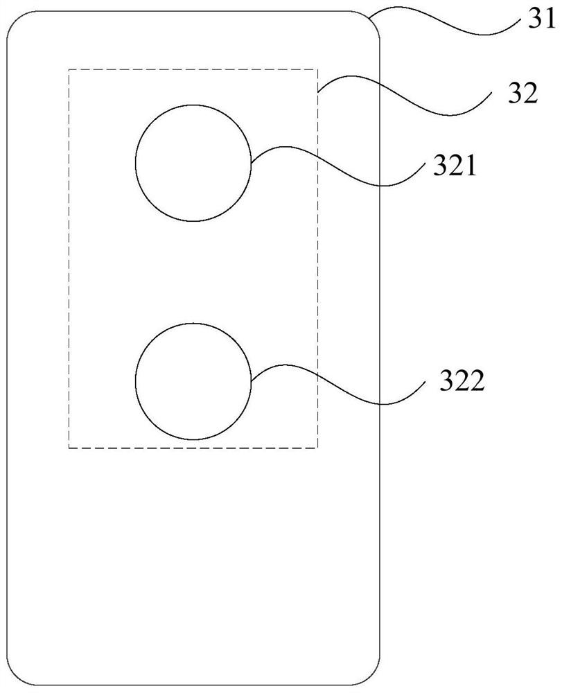
[0056] image 3 It is a schematic structural diagram of a charging device provided in Embodiment 2 of the present invention. The charging device may be any terminal device or a cover of a terminal device, including: a main body 31, and a charging electrode 32 disposed on the main body, wherein the charging electrode 32 includes a first charging electrode with a magnetic region 321 and a second charging electrode 322 having a magnetic region, the magnetic pole of the magnetic region of the first charging electrode 321 is opposite to that of the magnetic region of the second charging electrode 322 .
[0057] Further, the charging electrode is specifically used for: if the magnetic region of the charging electrode is at the N pole, then receive the positive current conducted by the charging device; if the magnetic region of the charging electrode is at the S pole, receive the positive current conducted by the charging device. negative current.
[0058] Further, the charging ele...
Embodiment 3
[0064] Figure 4 It is a schematic flowchart of a charging control method provided in Embodiment 3 of the present invention. The method is applied to the charging device provided by any of the above embodiments, and is suitable for charging a charging device. The method includes:
[0065] S410. Detect preset features of the charging electrodes disposed on the charging device through the detection unit.
[0066] S420. Using the control unit, according to the preset characteristics of the charging electrode, control the positive and negative polarities of the contact pins in contact with the charging electrode, so as to charge the charging device.
[0067] Further, the detection unit is a magnetic pole sensor, and the passing detection unit detects the preset characteristics of the charging electrodes arranged on the charging equipment, including: determining the charging electrodes according to the principle of like-sex repelling and opposite-sex attracting. Magnetic regions a...
PUM
 Abstract
Description
Claims
Application Information
 - R&D
- Intellectual Property
- Life Sciences
- Materials
- Tech Scout
- Unparalleled Data Quality
- Higher Quality Content
- 60% Fewer Hallucinations
Browse by: Latest US Patents, China's latest patents, Technical Efficacy Thesaurus, Application Domain, Technology Topic, Popular Technical Reports.
© 2025 PatSnap. All rights reserved.Legal|Privacy policy|Modern Slavery Act Transparency Statement|Sitemap|About US| Contact US: help@patsnap.com


