Push-pull decorative material unloading mechanism

A technology of decorative materials and unloading mechanism, which is applied in the field of decorative materials, can solve the problems of affecting the use effect, affecting production efficiency, and powdery decorative materials becoming lumpy, so as to reduce labor intensity, improve work efficiency, and reduce waste of resources. Effect

Inactive Publication Date: 2018-06-05
CHENGDU YALIAN TECH CO LTD
View PDF0 Cites 9 Cited by
  • Summary
  • Abstract
  • Description
  • Claims
  • Application Information

AI Technical Summary

Problems solved by technology

[0002] During the unloading process of powdery decorative materials, it is necessary to add an appropriate amount of liquid or semi-solid auxiliary materials for stirring to further form a mixture. After the stirring of this part of the material, it will enter the next process. The mixed material has a certain viscosity and is irregular. , The reliability of the unloader mechanism of the feeder has a great influence on the smoothness of the entire production process, which greatly affects the production efficiency. Generally, the unloading device simply performs mixed unloading, which cannot take into account the possible situations that may occur during unloading. When unloading, the sequence and dosage of powdery decorative materials and auxiliary materials need to be well adjusted. Improper adjustment will cause the powdery decorative materials to become lumps, which will greatly affect the use effect, and during the unloading process , there will be a phenomenon that the material sticks in the box, which will cause damage to the device for a long time, and, therefore, we propose a push-pull decorative material unloading mechanism

Method used


Image

  • Push-pull decorative material unloading mechanism
  • Push-pull decorative material unloading mechanism
  • Push-pull decorative material unloading mechanism

Examples


Embodiment Construction

[0019] The following will clearly and completely describe the technical solutions in the embodiments of the present invention with reference to the accompanying drawings in the embodiments of the present invention. Obviously, the described embodiments are only some, not all, embodiments of the present invention.

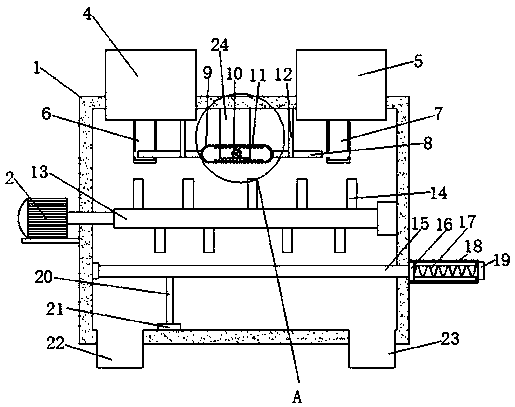
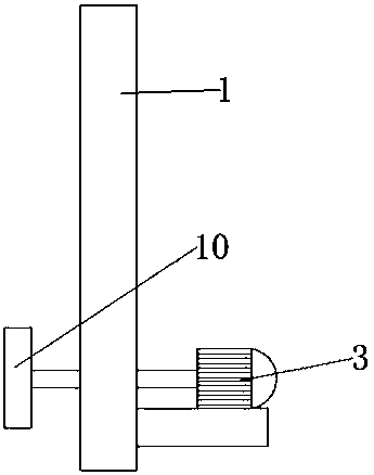
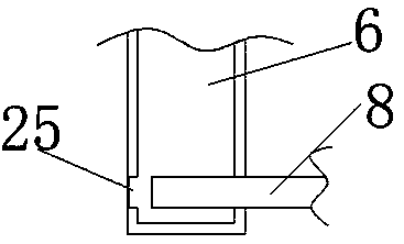
[0020] refer to Figure 1-7 , a push-pull decoration material unloading mechanism, comprising a box body 1, a decoration material storage box 4 is provided on the left side of the upper end of the box body 1, one end of the decoration material storage box 4 penetrates into the box body 1, and the decoration material storage box 4 The lower end of the box 4 is provided with a first discharge pipe 6, and the right side of the upper end of the box body 1 is provided with an auxiliary material storage box 5, and one end of the auxiliary material storage box 5 penetrates to the inside of the box body 1, and the lower end of the auxiliary material storage box 5 is provided ...


PUM


Abstract

The invention relates to the technical field of decorative materials and particularly relates to a push-pull decorative material unloading mechanism. The push-pull decorative material unloading mechanism comprises a tank body, wherein a decorative material storage tank is arranged on the left side of the upper end of the tank body, and an auxiliary material storage tank is arranged on the right side of the upper end of the tank body; an output shaft of a second motor penetrates through a fixed plate and is connected with a rotating shaft, and an incomplete gear is connected to one end, far from a second motor, of the rotating shaft; a frame body is arranged on opposite sides of two transverse rods, and racks meshed with the incomplete gear are symmetrically arranged on the inner wall of the frame body; and a support plate is arranged on one side of the tank body, a first motor is mounted at the upper end of the support plate, an output shaft of the first motor penetrates through the tank body and is connected with a rotating rod, a first discharging hole is formed in the left side of the lower end of the tank body, and the first motor and the second motor are connected with an external control switch. According to the push-pull decorative material unloading mechanism, a subsequent manual cleaning process is omitted, so the labor intensity of workers is reduced, and the workingefficiency is improved.

Description

technical field [0001] The invention relates to the technical field of decorative materials, in particular to a push-pull type decorative material unloading mechanism. Background technique [0002] During the unloading process of powdery decorative materials, it is necessary to add an appropriate amount of liquid or semi-solid auxiliary materials for stirring to further form a mixture. After the stirring of this part of the material, it will enter the next process. The mixed material has a certain viscosity and is irregular. , The reliability of the unloader mechanism of the feeder has a great influence on the smoothness of the entire production process, which greatly affects the production efficiency. Generally, the unloading device simply performs mixed unloading, which cannot take into account the possible situations that may occur during unloading. When unloading, the sequence and dosage of powdery decorative materials and auxiliary materials need to be well adjusted. Im...

Claims


Application Information

Patent Timeline
Patent Type & Authority Applications(China)
IPC IPC(8): B01F15/02B01F15/00B01F7/04
CPCB01F27/70B01F35/123B01F35/2211B01F35/717B01F35/754
Inventor 阮小彬
Owner CHENGDU YALIAN TECH CO LTD
Why Eureka
Try Eureka