Coordinated control method and device between synchronous condenser and LCC-HVDC

A technology of LCC-HVDC and coordinated control, which is applied in the field of coordinated control between synchronous condensers and LCC-HVDC, can solve problems such as weak resistance to commutation failure, and achieve the goal of improving resistance and reducing the probability of commutation failure Effect

Active Publication Date: 2021-05-14
STATE GRID CORP OF CHINA +1
View PDF6 Cites 0 Cited by
  • Summary
  • Abstract
  • Description
  • Claims
  • Application Information

AI Technical Summary

Problems solved by technology

[0006] In order to overcome the above-mentioned shortcomings of the weak ability to resist commutation failure of LCC-HVDC in the prior art, the present invention provides a method and device for coordinated control between the synchronous condenser and LCC-HVDC. First, the failure judgment module judges whether the AC system occurs Fault, if it is, calculate the cut-off angle deviation according to the cut-off angle of LCC-HVDC, then determine the voltage deviation according to the cut-off angle deviation, and calculate the synchronous condenser control input according to the voltage deviation, and finally determine the synchronization according to the synchronous condenser control input The excitation voltage of the condenser, and according to the excitation voltage of the synchronous condenser, the coordinated control between the synchronous condenser and the LCC-HVDC is realized, and the LCC-HVDC commutation failure resistance is improved through the coordinated control between the synchronous condenser and the LCC-HVDC ability

Method used


Image

  • Coordinated control method and device between synchronous condenser and LCC-HVDC
  • Coordinated control method and device between synchronous condenser and LCC-HVDC
  • Coordinated control method and device between synchronous condenser and LCC-HVDC

Examples


Embodiment Construction

[0045] The present invention will be described in further detail below in conjunction with the accompanying drawings.

[0046] The embodiment of the present invention provides a coordinated control method between a synchronous condenser and an LCC-HVDC. The structure diagram of an LCC-HVDC connected to a synchronous condenser is as follows figure 1As shown, the specific flow chart of the coordinated control method between the synchronous condenser and the LCC-HVDC is as follows figure 2 As shown, the specific process is as follows:

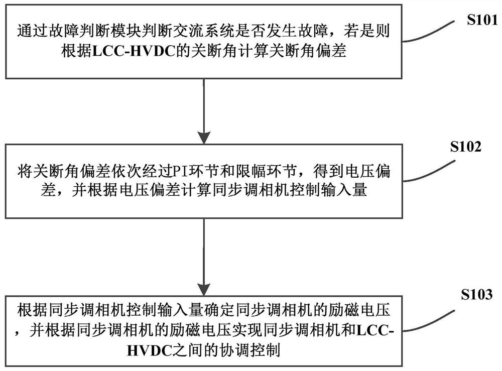
[0047] S101: Use the fault judgment module to judge whether the AC system has a fault, and if so, calculate the cut-off angle deviation according to the cut-off angle of the LCC-HVDC;

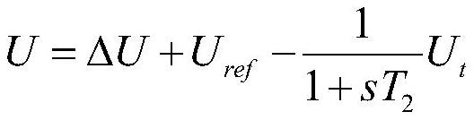
[0048] S102: Pass the turn-off angle deviation through the PI link and the limiting link in sequence to obtain the voltage deviation, and calculate the synchronous condenser control input amount according to the voltage deviation;

[0049] S103: Determine the ex...


PUM


Abstract

The present invention provides a coordinated control method and device between a synchronous condenser and an LCC-HVDC. First, a fault judgment module is used to judge whether the AC system is faulty, and if so, the off-angle deviation is calculated according to the off-angle of the LCC-HVDC, and then Determine the voltage deviation according to the turn-off angle deviation, and calculate the control input of the synchronous condenser according to the voltage deviation, and finally determine the excitation voltage of the synchronous condenser according to the control input of the synchronous condenser, and realize the synchronous condenser and the synchronous condenser according to the excitation voltage of the synchronous condenser. Coordinated control between LCC‑HVDC improves LCC‑HVDC commutation failure resistance through coordinated control between synchronous condensers and LCC‑HVDC. The technical solution provided by the invention can stabilize the bus voltage through the reactive power output by the synchronous condenser, improve the resistance to commutation failure of LCC-HVDC, and reduce the probability of commutation failure of LCC-HVDC.

Description

technical field [0001] The invention relates to the technical field of direct current transmission, in particular to a method and device for coordinated control between a synchronous condenser and an LCC-HVDC. Background technique [0002] Due to the significant development in the field of power electronics technology in recent years, line-commutated-converter high voltage direct current (LCC-HVDC) has attracted more and more attention. With its advantages in long-distance large-capacity power transmission, cross-strait power transmission, and interconnection of AC systems, it has been widely used around the world. However, since conventional DC transmission systems use thyristors without self-shutoff capability as commutation components, a certain strength of AC system is required to provide commutation voltage, which is prone to commutation failure. [0003] The process of commutation failure is as follows: the AC system fails, causing the AC and DC voltage to drop, the D...

Claims


Application Information

Patent Timeline
Patent Type & Authority Patents(China)
IPC IPC(8): H02J3/36H02J3/16
CPCH02J3/16H02J3/36Y02E40/30Y02E60/60
Inventor 黄勇王庆郭春义杨鹏程赵成勇杨硕
Owner STATE GRID CORP OF CHINA
Why Eureka
Try Eureka