Fiber fixing means for photoelectric device

A technology of optical fiber fixing device and photoelectric equipment, which is applied in the direction of light guide, optics, optical components, etc., can solve the problem of insufficient stability of the optical fiber connection state, and achieve the effect of ensuring the working state

Inactive Publication Date: 2018-05-29
天津凯莱斯光电设备有限公司
View PDF0 Cites 0 Cited by
  • Summary
  • Abstract
  • Description
  • Claims
  • Application Information

AI Technical Summary

Problems solved by technology

[0003] The purpose of the present invention is to solve the shortcomings of the prior art that the optical fiber of the optoelectronic equipment is fixed in a relatively simple way, and the connection state between the optical fibers is not stable enough, and proposes a fiber optic fixing device for optoelectronic equipment

Method used


Image

  • Fiber fixing means for photoelectric device
  • Fiber fixing means for photoelectric device
  • Fiber fixing means for photoelectric device

Examples


Embodiment Construction

[0020] The following will clearly and completely describe the technical solutions in the embodiments of the present invention with reference to the accompanying drawings in the embodiments of the present invention. Obviously, the described embodiments are only some, not all, embodiments of the present invention.

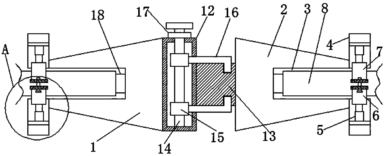
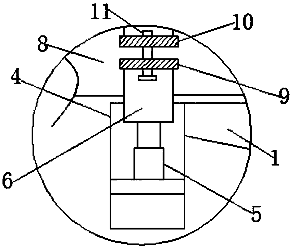
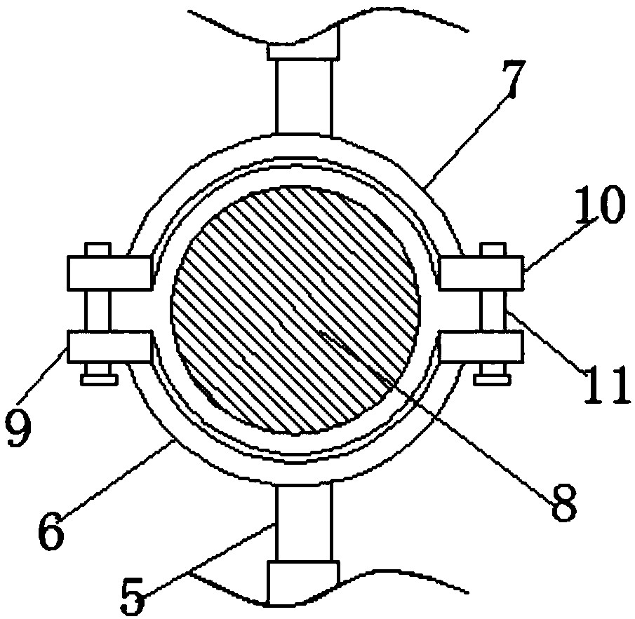
[0021] refer to Figure 1-3 , an optical fiber fixing device for optoelectronic equipment, comprising a first clamping block 1 and a second clamping block 2 arranged symmetrically, the first clamping block 1 and the second clamping block 2 are connected by a clamping device, and the clamping device includes a mounting block 12 With the third clamping block 13, the mounting block 12 is fixedly connected with the first clamping block 1, and the third clamping block 13 is fixedly connected with the second clamping block 2. The mounting block 12 is a hollow structure, and the mounting block 12 is provided with a vertical threaded rod 14, one end of the threaded rod 14 is...


PUM


Abstract

The invention discloses a fiber fixing means for a photoelectric device, comprising a first clamping block and a second clamping block, which are symmetrically arranged. The first clamping block and the second clamping block are connected through a clamping device. One side of the first clamping block and one side of the second clamping block, which are opposite to each other, are respectively provided with a fiber groove. Openings of the two fiber grooves are oppositely arranged. The internal parts of the two fiber grooves are respectively provided with a fiber and a signal converter. The fiber is connected to the signal converter. The openings of the two fiber grooves are respectively provided with two symmetrically-arranged fixing blocks, which are hollow structures. The fixing block isfixedly connected to a telescoping device, and the two telescoping devices both penetrate through the fixing blocks. The opposite sides of the two telescoping devices are respectively provided with afirst fixing plate and a second fixing plate. The invention is advantageous in that fibers in the photoelectric device can be stably fixed, and the work state of fibers can be ensured to be stable.

Description

technical field [0001] The invention relates to the technical field of optoelectronic equipment, in particular to an optical fiber fixing device for optoelectronic equipment. Background technique [0002] The optoelectronic industry is the sum of all kinds of parts, components, equipment and application markets composed of optoelectronic technology as the core. For all commercial activities, the equipment used in the optoelectronic industry is optoelectronic equipment. The optical fiber of the existing optoelectronic equipment is fixed in a relatively simple way, and the connection state between the optical fibers is not stable enough. Therefore, we propose a kind of optoelectronic equipment that is fixed with optical fibers. device to solve the above problems. Contents of the invention [0003] The purpose of the present invention is to solve the shortcomings of the optical fiber fixing method of the optoelectronic equipment in the prior art that the fixing method is rel...

Claims


Application Information

Patent Timeline
IPC IPC(8): G02B6/42
CPCG02B6/4243
Inventor 丁胜男
Owner 天津凯莱斯光电设备有限公司
Why Eureka
Try Eureka