
Ore separation equipment and conveying device thereof and ore conveying method

A technology of transmission device and transmission method, which is applied in sorting and other directions, and can solve problems such as low mining efficiency, difficult spacing control, and increased manual labor burden

Pending Publication Date: 2018-05-25
浙江力拓机电科技有限公司
View PDF11 Cites 3 Cited by
  • Summary
  • Abstract
  • Description
  • Claims
  • Application Information

AI Technical Summary

Problems solved by technology

[0003] Those skilled in the art can understand that in order to improve the efficiency and reliability of distinguishing ore into rich ore blocks and lean ore blocks, it is necessary to detect the ores one by one. After the ore is mined, it is usually stacked together. Therefore, before the economic significance of each ore is detected, each ore stacked together needs to be transported to the detection area to detect it. However, there is no equipment that realizes this function on the market at present, and there is Provide solutions and solutions to this problem. If the piles of ore are arranged into an ore flow manually, it will not only lead to very low mining efficiency, but also increase the labor burden of manpower, and A large number of manual participation in this process will also cause a substantial increase in mining costs
In addition, the spacing between adjacent ores arranged artificially is not easy to be controlled, which further leads to a decrease in the reliability of subsequent detection of each ore separately

Method used


Image

  • Ore separation equipment and conveying device thereof and ore conveying method
  • Ore separation equipment and conveying device thereof and ore conveying method
  • Ore separation equipment and conveying device thereof and ore conveying method

Examples


Embodiment Construction

[0062] The following description serves to disclose the present invention to enable those skilled in the art to carry out the present invention. The preferred embodiments described below are only examples, and those skilled in the art can devise other obvious variations. The basic principles of the present invention defined in the following description can be applied to other embodiments, variations, improvements, equivalents and other technical solutions without departing from the spirit and scope of the present invention.

[0063] Those skilled in the art should understand that in the disclosure of the present invention, the terms "vertical", "transverse", "upper", "lower", "front", "rear", "left", "right", " The orientation or positional relationship indicated by "vertical", "horizontal", "top", "bottom", "inner", "outer", etc. is based on the orientation or positional relationship shown in the drawings, which are only for the convenience of describing the present invention...


PUM


Abstract

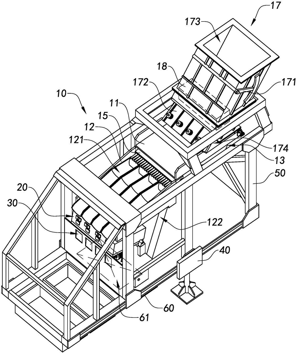
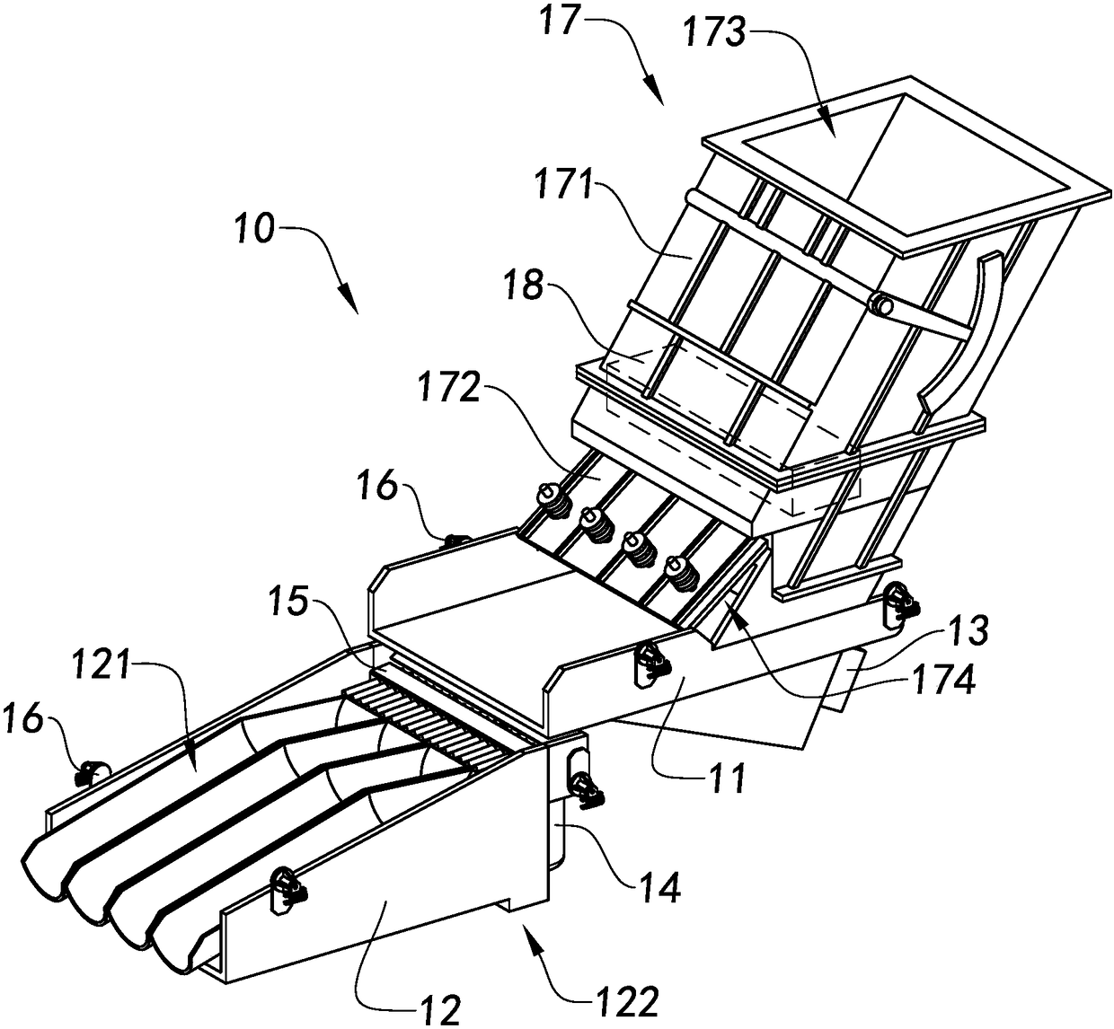
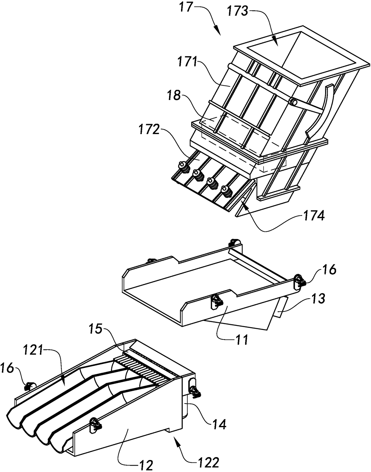
The invention provides ore separation equipment and a conveying device thereof and an ore conveying method. The conveying device comprises at least one separator, wherein the separator is provided with at least one separation groove, the separation groove extends between the inlet end and the outlet end of the separator, and the inlet end of the separator is higher than the outlet end. When ore enters the separation groove from the inlet end of the separator, ore streams are formed, and each piece of ore forming the ore streams is separated from the separation groove from the outlet end of theseparation one by one, so that the ore is conveyed.

Description

technical field [0001] The invention relates to the field of ore sorting, in particular to an ore sorting device, a transmission device thereof, and an ore transmission method. Background technique [0002] The mining industry is a category of industry that extracts ores, which provide very important ore raw materials. According to the economic significance of ores, ores can be roughly divided into rich ore blocks and lean ore blocks. For example, according to the difference in metal content, ores with high metal content can be defined as rich ore blocks and ores with low metal content can be defined. For lean ore blocks. It can be understood that in the process after the ore is mined, the higher the proportion of rich ore blocks in the ore, the more the cost of beneficiation can be reduced. But the actual situation is that after the ore is mined, the rich ore block and the lean ore block are mixed together so that the proportion of the rich ore block in the ore is not hig...

Claims


Application Information

Patent Timeline
IPC IPC(8): B07C5/02
CPCB07C5/02
Inventor 肖健锋
Owner 浙江力拓机电科技有限公司
Learn More