Anti-wear push-pull switch

A push-pull, wear-resistant technology, applied in the field of switches, can solve the problems of high cost of timing function and easy damage of pressing device, and achieve the effect of avoiding the replacement of push-pull rods, convenient replacement and cost saving

Inactive Publication Date: 2018-05-18
CHENGDU KECHUANGCHENG TECH
View PDF5 Cites 0 Cited by
  • Summary
  • Abstract
  • Description
  • Claims
  • Application Information

AI Technical Summary

Problems solved by technology

[0004] Based on the above technical problems, the present invention provides an anti-wear push-pull switch, thereby solving the problem that the existing toilet exhaust fan and other electrical appliances have high cost of timing function, and the control system on each electrical appliance can only control the respective electrical appliances and The technical problem that the pressing device is easily damaged

Method used


Image

  • Anti-wear push-pull switch
  • Anti-wear push-pull switch
  • Anti-wear push-pull switch

Examples


Embodiment 1

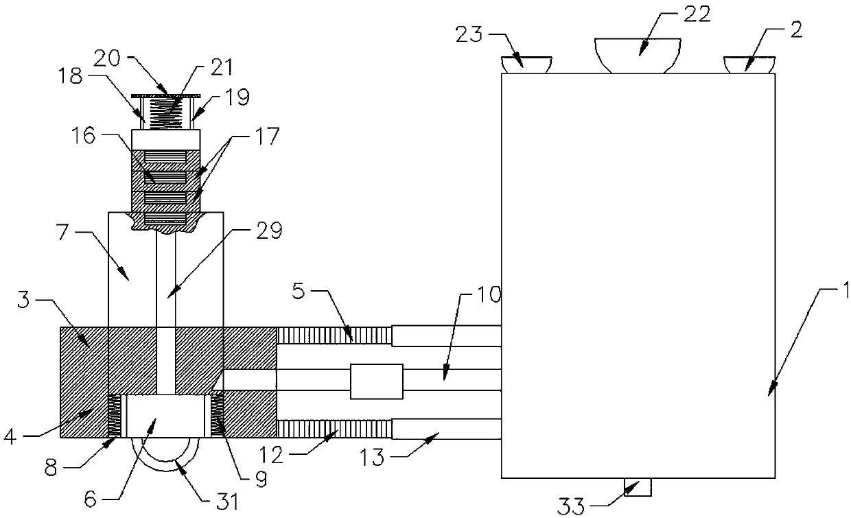
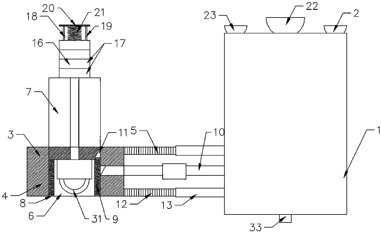
[0053] An anti-wear push-pull switch, comprising a timing switch body 1, the rear side of the timing switch body 1 is provided with an adsorption device 2 for connecting with a wall, and a side of the timing switch body 1 is provided with a switch device 3;

[0054] The switch device 3 includes a base 4, a connecting rod 5 is horizontally arranged between the base 4 and the timing switch body 1, and a through hole 6 is arranged inside the base 4, and the base 4 is located at the position of the through hole 6 and is provided with a hole suitable for the through hole 6. Equipped with a push-pull rod 7, the side of the base 4 away from the adsorption device 2 is located inside the through hole 6 with an annular baffle 8, and a first spring 9 is provided between the baffle 8 and the push-pull rod 7;

[0055] A crossbar 10 is arranged between the push-pull rod 7 and the timing switch body 1, and the timing switch body 1 controls the crossbar 10 to move in the horizontal direction; ...

Embodiment 2

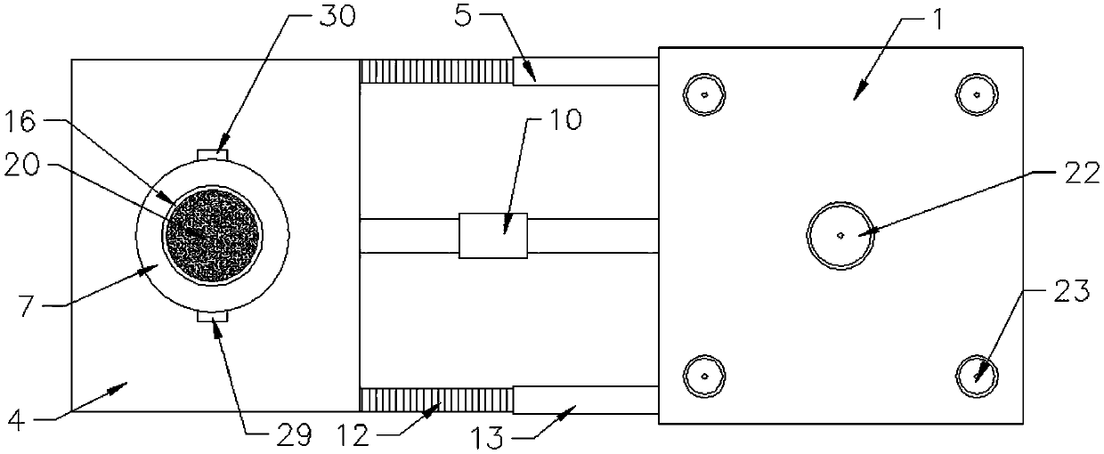
[0061] This embodiment is further optimized based on Embodiment 1. The outer wall of the push-pull rod 7 is evenly distributed with a plurality of guide rods 29 parallel to the length direction of the push-pull rod 7. The base 4 is provided with a guide groove 30 corresponding to the position of the guide rod 29, and the guide rod 29 And the guide groove 30 can not only guide the push-pull rod 7 during the movement of the push-pull rod 7, but also prevent the push-pull rod 7 from rotating, so as to facilitate the connection of the groove 11 and the cross bar 10.

Embodiment 3

[0063] This embodiment is further optimized based on Embodiment 1. The push-pull rod 7 is provided with a pull ring 31 on one side of the first spring 9, so that the push-pull rod 7 can be stretched conveniently.


PUM


Abstract

The invention relates to the technical field of switches and discloses an anti-wear push-pull switch, which comprises a timing switch body, wherein an adsorption device is arranged at the rear part ofthe timing switch body; a switch device is arranged at one side of the timing switch body and comprises a base; a push-pull rod is arranged in the base; a spring is arranged at the bottom of the push-pull rod; a cross rod is arranged between the push-pull rod and the timing switch body; a groove corresponding to the cross rod is arranged in the push-pull rod; a buffer device is arranged at the top of a base assembly and comprises a slide bar capable of extending into the base assembly; a flat panel is arranged at the top of the slide bar; and a second spring is arranged between the flat paneland the base assembly. The anti-wear push-pull switch is simple in structure, low in cost and convenient to assemble and dissemble, and can be used for controlling multiple devices; the service lifeof to-be-controlled switch and flat panel can be prolonged through the buffer device; the requirements of the adsorption device on an adsorption environment are relatively low; and the adsorption stability is good.

Description

technical field [0001] The invention relates to the technical field of switches, in particular to an anti-wear push-pull switch. Background technique [0002] At present, in the bathrooms of urban housing, exhaust fans are installed in the bathrooms for the convenience of discharging the odor from the bathrooms, but most of the exhaust fans are manual switches. The exhaust fan is turned off, and people usually forget to turn off the exhaust fan when they are busy with other things after going to the toilet, resulting in energy waste; since people usually go to sleep directly after going to the toilet at night, the exhaust fan cannot be turned on at this time The air fan has become a headache. If it is turned on, it can only be turned off in the morning, resulting in a waste of energy; if it is not turned on, when other people go to the toilet, the smell in the bathroom will be stinky, making others miserable; [0003] There is also a switch that controls the energization of...

Claims


Application Information

Patent Timeline
Patent Type & Authority Applications(China)
IPC IPC(8): H01H43/02H01H43/04
CPCH01H43/02H01H43/022H01H43/04
Inventor 雍海燕
Owner CHENGDU KECHUANGCHENG TECH
Why Eureka
Try Eureka