
Unmanned plane real time obstacle avoidance method based on binocular visual sense technology

A binocular vision, unmanned aerial vehicle technology, applied in photogrammetry/video surveying, measuring device, mapping and navigation, etc., can solve the problem of limited detection distance and range, low accuracy, missed detection and false detection, etc. problem, to achieve the effect of fast and stable autonomous obstacle avoidance

Active Publication Date: 2018-05-18
南京奇蛙智能科技有限公司
View PDF8 Cites 18 Cited by
  • Summary
  • Abstract
  • Description
  • Claims
  • Application Information

AI Technical Summary

Problems solved by technology

At present, there are a few UAV companies that install millimeter-wave radar, ultrasonic radar, optical flow, infrared and other sensors on UAVs for obstacle avoidance applications. Causing unexpected situations such as missed detection and false detection
In addition, there are currently related studies on UAV obstacle avoidance judgment through binocular vision, but most of them have not been well integrated with the flight control system due to control strategy problems, and the control of pitch, yaw, and roll is naturally and stably Integrate into the system control loop

Method used


Image

  • Unmanned plane real time obstacle avoidance method based on binocular visual sense technology
  • Unmanned plane real time obstacle avoidance method based on binocular visual sense technology
  • Unmanned plane real time obstacle avoidance method based on binocular visual sense technology

Examples


Embodiment 1

[0052] A real-time obstacle avoidance method for unmanned aerial vehicles based on binocular vision technology. The binocular vision real-time obstacle avoidance system includes an unmanned aerial vehicle body, a remote controller, an embedded computing platform Jetson TX2 and a binocular camera arranged on the unmanned aerial vehicle body. The binocular camera is fixed in front of the UAV, and the collected depth images are transmitted to the onboard computing unit Jetson TX2 in real time, and then judged by the preset obstacle avoidance strategy to generate evasive actions; if at the same time, a remote control is sent For the operation, priority judgment is required. Such as image 3 shown.

[0053] The method of UAV real-time obstacle avoidance based on this system, such as Figure 4 shown, including the following steps:

[0054] 1) Collect the disparity map through the binocular camera, perform three-dimensional reconstruction, and calculate the depth;

[0055] 2) Inc...

Embodiment 2

[0092] In this embodiment, the filling rate threshold a=60%, b=20%, and the relative measurement error threshold is set to C=5%. Other parts are the same as in the examples.

Embodiment 3

[0094] In this embodiment, the filling rate threshold a=40%, b=70%, and the relative measurement error threshold is set to C=1%. Other parts are the same as in the examples.


PUM


Abstract

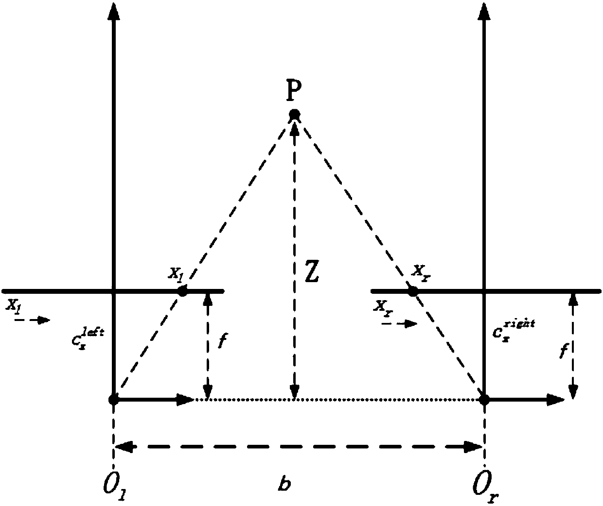
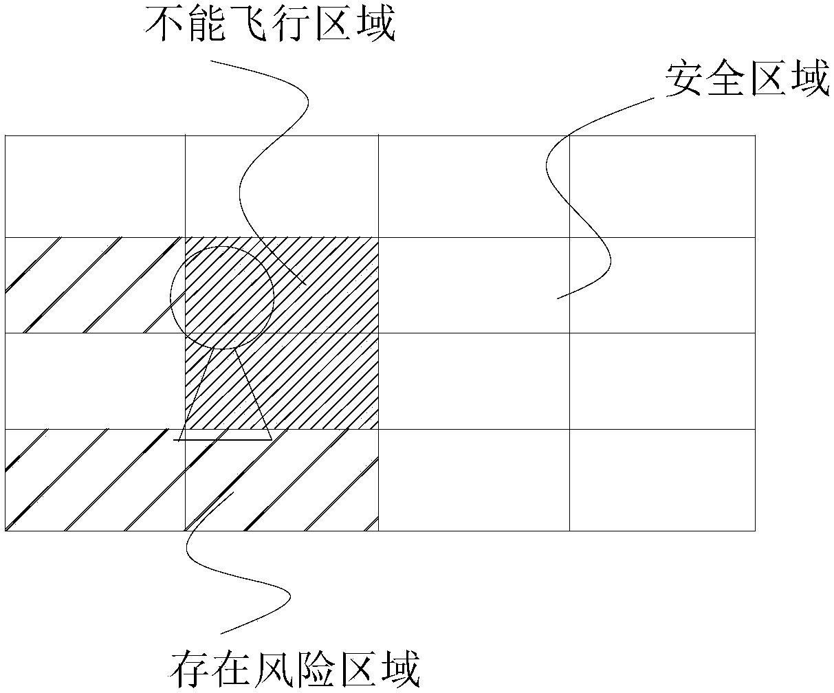
The invention discloses an unmanned plane real time obstacle avoidance method based on the binocular visual sense technology; the method comprises the following steps: 1, using a binocular camera to gather parallax images, carrying out three dimensional reconstruction, and calculating the depth; 2, increasing the threshold, and only identifying obstacles in a scope smaller than the obstacle avoidance radius Zmax; 3, traversing the images, and calculating the obstacle condition of each pixel point; 4, calculating the obstacle filling rate in each grid unit; if the filing rate is >50%, an obstacle is considered to exist; if the filling rate is between 10-50%, an obstacle is unknown and risks exist; if the filling rate is smaller than 10%, the condition is considered safe; 5, analyzing the safety area size and distribution conditions, thus outputting front-back, left-right and up-down motion speeds, and a rotary angle rate of the controlled unmanned plane; 6, allowing a user to control aremote controller while carrying out binocular visual sense obstacle avoidance, thus forming extra front-back, left-right and up-down motion speeds v of the unmanned plane, forming the rotary angle rate [omega], naturally stably fusing with the flight control system, and fast and stably carrying out autonomous obstacle avoidance.

Description

technical field [0001] The invention belongs to the field of unmanned aerial vehicle flight control, in particular to a real-time obstacle avoidance method for unmanned aerial vehicles based on binocular vision. Background technique [0002] With the development of the drone market, higher and higher requirements are put forward for the automatic perception and control of drones, especially in the aspect of active obstacle avoidance, so that drones can fly autonomously and safely in complex environments without accidents. Collision and bombing situation. At present, there are a few UAV companies that install millimeter-wave radar, ultrasonic radar, optical flow, infrared and other sensors on UAVs for obstacle avoidance applications. Unexpected situations such as missed detection and false detection are caused. In addition, there are currently related studies on UAV obstacle avoidance judgment through binocular vision, but most of them have not been well integrated with the...

Claims


Application Information

Patent Timeline
Patent Type & Authority Applications(China)
IPC IPC(8): G05D1/10G01C11/00
CPCG01C11/00G05D1/101G01C11/36
Inventor 廖振星段文博高月山张伟
Owner 南京奇蛙智能科技有限公司
Learn More