Visual sense measuring instrument and visual sense measuring method

A visual measurement and instrument technology, applied in the field of visual measurement, can solve problems such as misalignment, narrow field of view, and undetermined positional relationship, and achieve the effects of improving accuracy and solving horizontal attitude and height difference

Pending Publication Date: 2018-05-18
DONGGUAN NEUTRON SCI CENT
View PDF0 Cites 8 Cited by
  • Summary
  • Abstract
  • Description
  • Claims
  • Application Information

AI Technical Summary

Problems solved by technology

[0005] 1. The main optical axis of the TS16 camera is not coaxial with the collimation axis of the total station, and the focal point or image plane of the camera has no definite positional relationship with the instrument center point of the total station;
[0006] 2. The main parameters of TS16 camera are: 5 million pixels, field of view is 19.4°, camera sensor and lens have low resolution and narrow field of view
Although TS16 can determine the relationship between the principal optical axis and the collimation axis and the positional relationship between the focal point or image plane of the camera and the instrument center point of the total station through the method of self-calibration by the user, the movement of the horizontal dial and the vertical dial Under the combined effect, the complexity of the system is greatly increased, and it is impossible to achieve higher precision

Method used


Image

  • Visual sense measuring instrument and visual sense measuring method
  • Visual sense measuring instrument and visual sense measuring method
  • Visual sense measuring instrument and visual sense measuring method

Examples


Embodiment Construction

[0049] The present application will be described in further detail below through specific embodiments in conjunction with the accompanying drawings. The present application can be realized in many different forms, and is not limited to the implementation manner described in this embodiment. The purpose of providing the following specific embodiments is to facilitate a clearer and more thorough understanding of the disclosure of the present application, wherein the words indicating orientation such as up, down, left, and right are only for the positions of the structures shown in the corresponding drawings.

[0050] However, those skilled in the art may recognize that description of one or more of the specific details may be omitted, or other methods, components or materials may also be used. In some instances, some implementations were not described or described in detail.

[0051] In addition, the technical features and technical solutions described herein can also be combin...


PUM


Abstract

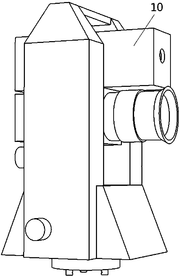
The application discloses a visual sense measuring instrument and a visual sense measuring method; the visual sense measuring instrument comprises a machine body, a horizontal circle, a vertical circle, a lens, an image sensor and a horizontal sensor, a distance sensor, a horizontal direction adjusting turn button and a vertical direction adjusting turn button; the central axle of the horizontal circle and the primary optic axis of the lens are respectively vertical to the central axis of the vertical circle; the central axle of the horizontal circle, the primary optic axis of the lens and thecentral axis of the vertical circle intersect in one point; the primary optic axis of the lens vertically intersects with the image plane of the image sensor; the range finding optical axis of the distance sensor and the primary optic axis of the lens parallel or overlap, and intersect with the central axle of the horizontal circle; the line array of a photosensitive unit array of the image sensor is parallel to the central axis of the vertical circle; the column array of the photosensitive unit array of the image sensor is vertical to the central axis of the vertical circle; the central axleof the horizontal sensor is parallel to the central axle of the horizontal circle. The visual sense measuring instrument and method are non-contact, high in precision, high in efficiency, and can improve the photogrammetry precision.

Description

technical field [0001] The present application relates to the technical field of visual measurement, in particular to a visual measurement instrument and a visual measurement method. Background technique [0002] For the spatial three-dimensional size and position measurement of the measured object, a laser tracker system or a digital close-range photogrammetry system are generally used. The laser tracker system obtains the spatial information of the measured object through the dial measurement angle and laser distance measurement, which has the advantages of high precision and strong reliability. The digital close-range photogrammetry system obtains more than two images of the same object in different positions and directions through the camera, and obtains the precise three-dimensional coordinates of the point to be measured after image processing and matching and other related mathematical calculations. It has non-contact, high efficiency, etc. Significant advantages. ...

Claims


Application Information

Patent Timeline
IPC IPC(8): G01B11/00G01C11/00
CPCG01B11/00G01C11/00
Inventor 董岚王铜梁静罗涛朱洪岩柯志勇何振强马娜李波王小龙门玲鸰
Owner DONGGUAN NEUTRON SCI CENT
Why Eureka
Try Eureka