Ornithopter transmission component based on Y-shaped structure and implementation method
A flapping-wing aircraft and transmission component technology, applied in the field of flapping-wing aircraft transmission components, can solve the problems of easy deformation and damage of the main wing spar of the wing, unstable flapping, redundant rotational freedom of the transmission rocker, etc. Rotational degrees of freedom, improved stress conditions, and improved bearing capacity
- Summary
- Abstract
- Description
- Claims
- Application Information
AI Technical Summary
Problems solved by technology
Method used
Image
Examples
Embodiment 1
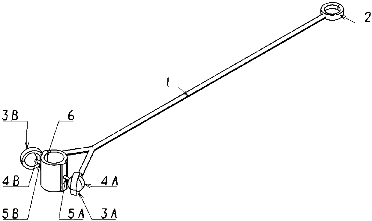
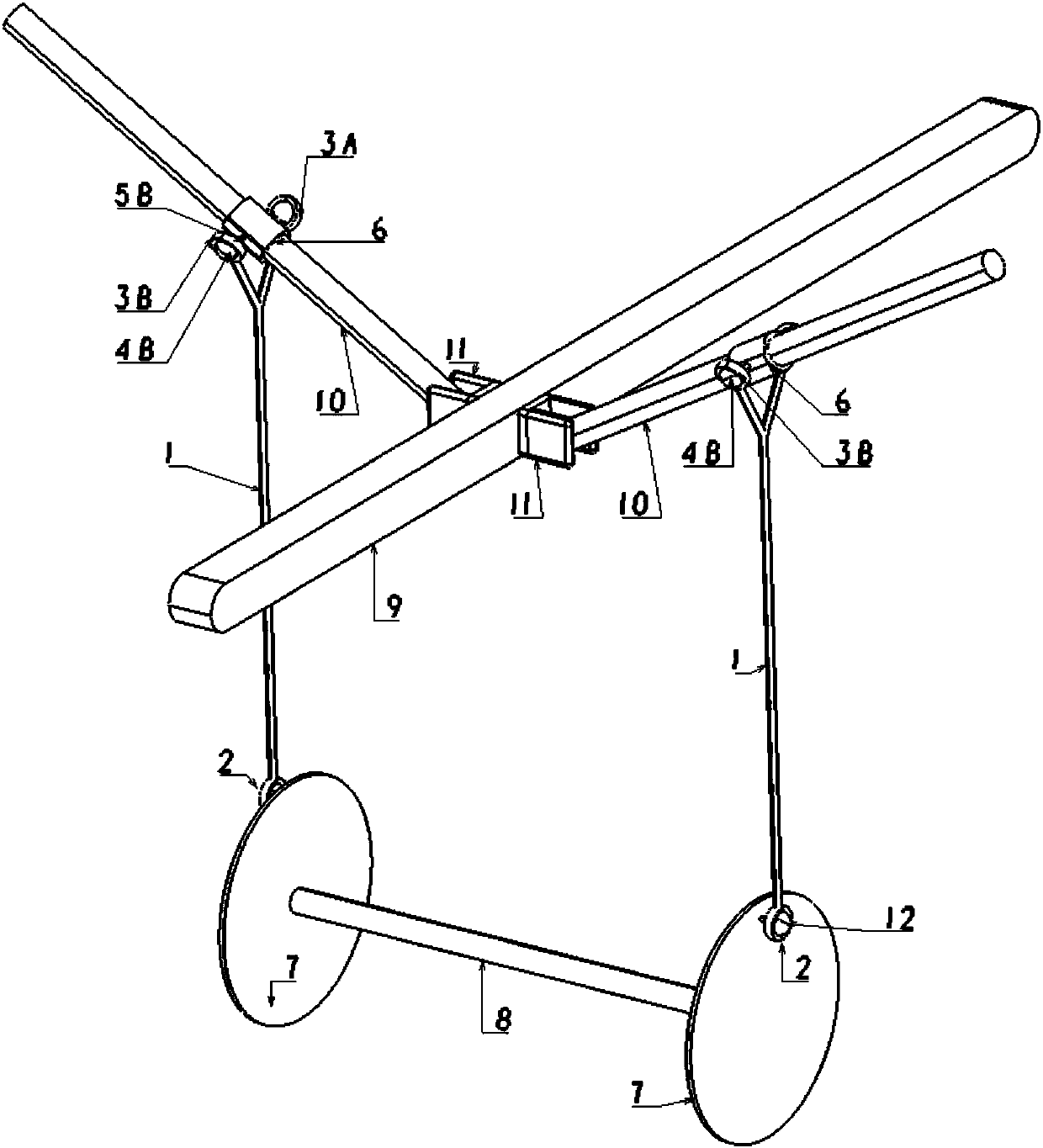
[0050] In a typical implementation of the present application, such as figure 1 , figure 2 , image 3 As shown, a transmission part of a flapping-wing aircraft based on a Y-shaped structure includes a transmission rocker 1. One end of the transmission rocker 1 is arranged in a V shape, and the other end is a spherical bearing I connected with the drive wheel 7. The transmission rocker V Both sides of the type end are provided with a spherical bearing II connected with the wing main spar 10. The transmission part replaces the existing "one"-shaped transmission part through the Y-shaped transmission rocker 1, and the Y-shaped transmission rocker applies force to the wing main spar from both sides of the V-shaped end of the transmission rocker respectively, so that the wing The force on both sides of the main spar is more stable and even, which reduces the damage to the wing main spar 10 and prolongs the service life of the wing main spar 10. Moreover, the plane formed by the...
Embodiment 2
[0061] Such as Image 6 As shown, the difference between this embodiment and Embodiment 1 is: in this embodiment, the transmission rocker is the rib transmission rocker 14, the rib 13 that is rotatably engaged with the wing main spar 10, and the rolling ball III 12 passes through the Z-shaped crank 15 1. The spherical sub-structure is connected to the bottom of the rib transmission rocker 14, and the top of the rib transmission rocker 14 is connected to the rib 13 through a sliding bearing, wherein the plane formed by the two sides of the V-shaped end of the rib transmission rocker 14 and The bottom spherical bearings are arranged on different surfaces, and the angle formed is 90°.
Embodiment 3
[0063] In order to overcome the deficiencies of the prior art, the present invention also provides a flapping-wing structure of a bionic flapping-wing aircraft, including a transmission part of the flapping-wing aircraft based on a Y-shaped structure described in Embodiment 1 or Embodiment 2.
[0064] The transmission structure also includes:
[0065] The drive shaft is provided with a drive wheel at each end;
[0066] The rotating base, the end of the wing main spar is connected with the fuselage main frame through the rotating base, and the wing main spar is rotatably arranged relative to the rotating base.
[0067] There are two rotating bases, which are symmetrically arranged on both sides of the main frame of the fuselage.
[0068] The rotating base is a door frame structure, the rotating base is fixedly connected with the main frame of the fuselage, the rotating pin is arranged in the rotating base, and the end of the main spar of the wing is rotatably engaged with the ...
PUM
 Abstract
Description
Claims
Application Information
 - R&D
- Intellectual Property
- Life Sciences
- Materials
- Tech Scout
- Unparalleled Data Quality
- Higher Quality Content
- 60% Fewer Hallucinations
Browse by: Latest US Patents, China's latest patents, Technical Efficacy Thesaurus, Application Domain, Technology Topic, Popular Technical Reports.
© 2025 PatSnap. All rights reserved.Legal|Privacy policy|Modern Slavery Act Transparency Statement|Sitemap|About US| Contact US: help@patsnap.com


