
Device for fixing cabinet

A technology for fixing cabinets and fixing plates, which is applied in the directions of cabinets/boxes/drawer parts, electrical equipment casings/cabinets/drawers, electrical components, etc. Easy disassembly, increased range effect

Inactive Publication Date: 2018-05-08
朱康明
View PDF0 Cites 0 Cited by
  • Summary
  • Abstract
  • Description
  • Claims
  • Application Information

AI Technical Summary

Problems solved by technology

[0005] The purpose of the present invention is to solve the problems of complicated installation and inconvenient disassembly in the prior art, and propose a device for fixing the cabinet

Method used

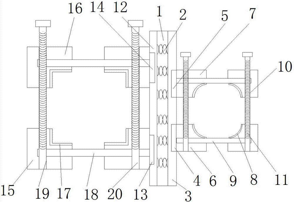

Image

  • Device for fixing cabinet
  • Device for fixing cabinet
  • Device for fixing cabinet

Examples


Embodiment Construction

[0019] The following will clearly and completely describe the technical solutions in the embodiments of the present invention with reference to the accompanying drawings in the embodiments of the present invention. Obviously, the described embodiments are only some, not all, embodiments of the present invention.

[0020] In describing the present invention, it should be understood that the terms "upper", "lower", "front", "rear", "left", "right", "top", "bottom", "inner", " The orientation or positional relationship indicated by "outside", etc. is based on the orientation or positional relationship shown in the drawings, and is only for the convenience of describing the present invention and simplifying the description, rather than indicating or implying that the referred device or element must have a specific orientation, so as to Specific orientation configurations and operations, therefore, are not to be construed as limitations on the invention.

[0021] refer to Figure ...


PUM


Abstract

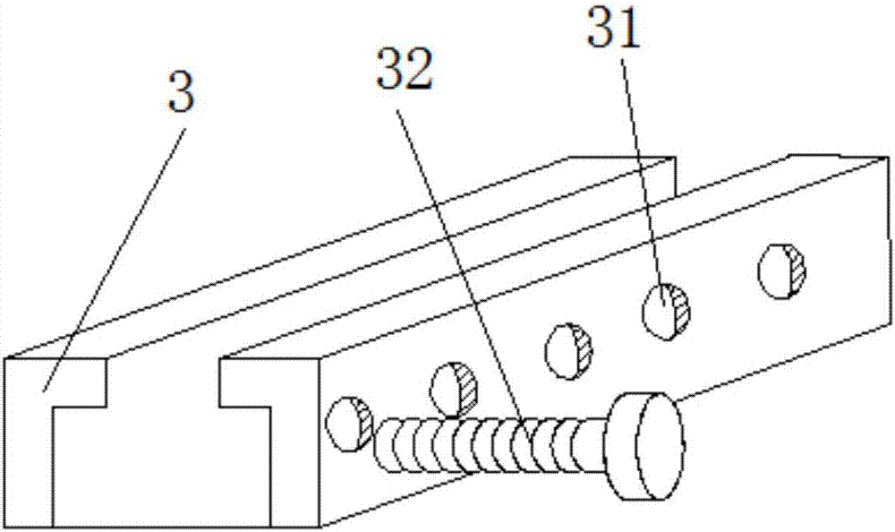
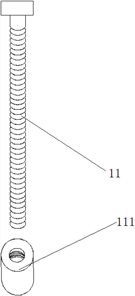
The invention discloses a device for fixing a cabinet. The device comprises a fixing plate with a hollow inner cavity. A spring is fixedly connected to the inner cavity of the fixing plate. The sidewall on one side of the fixing plate is successively connected with a plurality of concave sliding chutes 1 in the vertical direction. The inner wall of each concave sliding chute 1 is successively sleeved with a first convex slide block and a second convex slide block in the horizontal direction. The sides, away from the concave sliding chutes 1, of the first convex slide block and the second convex slide block are connected with a first concave fixing block and a second concave fixing block respectively. Wear resistance layers are disposed at the grooves of the first concave fixing block and the second concave fixing block. Telescopic plates 1 are installed at the middles of the first concave fixing block and the second concave fixing block. Through holes 1 are disposed at corresponding positions of the first concave fixing block and the second concave fixing block. The device for fixing a cabinet is simple in structure and convenient to operate, and can conveniently fix and disassemble the cabinet.

Description

technical field [0001] The invention relates to the technical field of cabinet fixing, in particular to a device for fixing a cabinet. Background technique [0002] As an integral part of automated production, control cabinets include electrical control cabinets, frequency conversion control cabinets, etc. [0003] In the current assembly line assembly process, most of the control cabinets are ordinary vertical control cabinets, which are placed next to the machinery. Every time the assembly line is successfully debugged, it needs to be dismantled and transported to the customer's factory for assembly and debugging. However, due to site constraints, installation is inconvenient and It is inconvenient to disassemble, and the working environment during the assembly and debugging process is very unsatisfactory, which consumes a lot of time and is very inefficient. [0004] According to the above problems, the present invention designs a cabinet fixing device that is fast and e...

Claims


Application Information

Patent Timeline
Patent Type & Authority Applications(China)
IPC IPC(8): H05K5/02
CPCH05K5/0204H05K5/0217
Inventor 朱康明
Owner 朱康明
Learn More