
Locking and disengaging structure used for gun cartridge magazine and having two-way operation function

A two-way operation and magazine technology, applied in the field of firearms, can solve the problems of reducing the speed of changing magazines for users, operating comfort, and unsmooth operation, and achieve the effect of improving speed and operating comfort

Pending Publication Date: 2018-05-01
CHONGQING JIANSHE IND GRP
View PDF0 Cites 1 Cited by
  • Summary
  • Abstract
  • Description
  • Claims
  • Application Information

AI Technical Summary

Problems solved by technology

[0002] At present, the locking and releasing structures of pistol magazines in our country are all locked and released by using magazine rivets, which are only designed to meet the convenience of right-handed operation, but in actual use, sometimes left and right hands alternately use pistols. situation, and the situation that a large number of "left-handed" groups use pistols, the magazine lock and release structure that is only convenient for right-handed operation is not easy to operate in various situations, which reduces the speed and comfort of the user's magazine replacement sex

Method used


Image

  • Locking and disengaging structure used for gun cartridge magazine and having two-way operation function
  • Locking and disengaging structure used for gun cartridge magazine and having two-way operation function
  • Locking and disengaging structure used for gun cartridge magazine and having two-way operation function

Examples


Embodiment Construction

[0030] Embodiments of the present invention will be described in further detail below in conjunction with the accompanying drawings.

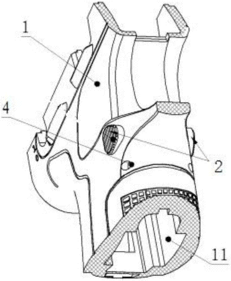
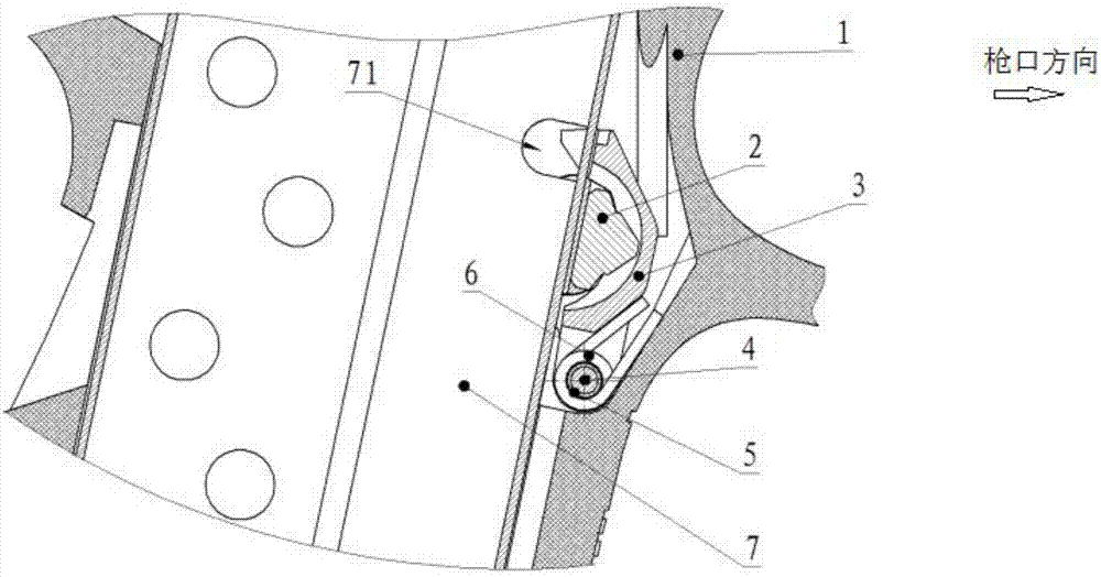
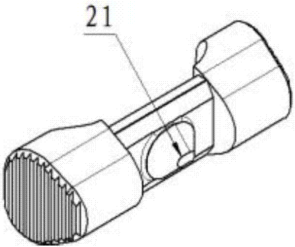
[0031] see Figure 1-Figure 13 , an embodiment of the two-way locking and releasing structure of the pistol magazine, an embodiment of the two-way locking and releasing structure of the pistol magazine, including a handle 1, and the front wall of the magazine slot 11 of the handle 1 is provided with There is a groove 14 (pointing to the front in the direction of the muzzle), the left and right side walls of the groove 14 are pierced with a magazine tenon pin 4, a magazine buckle 2 that can move left and right, and the magazine tenon pin 4 is worn on the top. A torsion spring 6 and a magazine tenon 3 that can be turned back and forth are provided. One spring foot of the torsion spring 6 is in contact with the magazine tenon 3, and the other spring foot of the torsion spring 6 is in contact with the groove bottom of the groove 14. Then, the uppe...


PUM


Abstract

The invention discloses a locking and disengaging structure used for a gun cartridge magazine and having a two-way operation function and belongs to the field of guns. The locking and disengaging structure comprises a handle; a groove is formed in the front wall face of a cartridge magazine inserting groove of the handle; cartridge magazine clamping tenon pins and cartridge magazine buckles capable of moving leftwards and rightwards are arranged on the left side wall and the right side wall of the groove in a penetrating mode; torsion springs and cartridge magazine clamping tenons capable of being turned over frontwards and backwards are arranged on the cartridge magazine clamping tenon pins in a penetrating mode; one torsion foot of each torsion spring abuts against the corresponding cartridge magazine clamping tenon, and the other torsion foot of each torsion spring abuts against the bottom of the groove; clamping teeth are arranged on the upper portions of the cartridge magazine clamping tenons and clamped into rivet holes of the cartridge magazine; conical bulged nipples are arranged in the middles of the cartridge magazine buckles, and V-shaped grooves for clamping the bulgednipples are formed in the middles of the cartridge magazine clamping tenons; and the two side walls of each V-shaped groove correspond to the left side face and the right side face of each bulged nipple. When moving leftwards and rightwards, the cartridge magazine buckles drive the cartridge magazine clamping tenons to be turned over forwards, and thus the clamping teeth of the cartridge magazineclamping tenons are disengaged from the rivet holes of the cartridge magazine.

Description

technical field [0001] The invention belongs to the field of firearms and relates to a bidirectionally operable locking and releasing structure of a pistol magazine. Background technique [0002] At present, the locking and releasing structures of pistol magazines in our country are all locked and released by using magazine rivets, which are only designed to meet the convenience of right-handed operation, but in actual use, sometimes left and right hands alternately use pistols. situation, and the situation that a large number of "left-handed" groups use pistols, the magazine lock and release structure that is only convenient for right-handed operation is not easy to operate in various situations, which reduces the speed and comfort of the user's magazine replacement sex. Contents of the invention [0003] The purpose of the present invention is to overcome the deficiencies of the prior art and provide a bidirectionally operable locking and releasing structure for a pisto...

Claims


Application Information

Patent Timeline
IPC IPC(8): F41A9/61
CPCF41A9/61
Inventor 郭新朋徐付波谢凤李良刚赵渝江周飞周云飞王明君
Owner CHONGQING JIANSHE IND GRP
Learn More