
One-stroke intermittent power supply motor

A motor and stroke technology, applied in the direction of electric components, electromechanical transmission devices, electrical components, etc., can solve problems such as continuous power supply, and achieve the effect of improving efficiency and saving electric energy

Inactive Publication Date: 2018-04-27
马明祥
View PDF0 Cites 0 Cited by
  • Summary
  • Abstract
  • Description
  • Claims
  • Application Information

AI Technical Summary

Problems solved by technology

[0003] At present, it is known that: 1. The motor does work by generating a rotating magnetic field after the armature winding is energized, and its disadvantage is that it needs continuous power supply to work normally; 2. The name of the invention is "Two-Stroke Permanent Magnet Motor", and the application (patent) number is 2010105520625 , The authorized announcement number is the invention patent of 102468786B. Its principle is to use the positive repulsion of the moving magnet (permanent magnet) and the fixed magnet (energized electromagnet) to complete a stroke, and use the moving magnet (permanent magnet) and the core of the power-off electromagnet The positive attraction of the moving magnet completes another stroke, and the reciprocating linear motion passes the connecting rod to rotate the crankshaft to output power. The disadvantage is that only one end of the moving magnet is stressed.

Method used


Image

  • One-stroke intermittent power supply motor
  • One-stroke intermittent power supply motor

Examples


Embodiment Construction

[0016] Below in conjunction with accompanying drawing, the present invention will be further described:

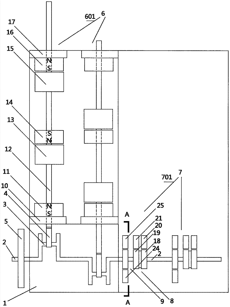
[0017] figure 1 Among them, include frame 1 and crankshaft 2 installed on frame 1, flywheel 5, magnetic drive unit group 6 and control unit group 7, magnetic drive unit group 6 includes at least one group of magnetic drive unit 601 (in the figure two groups Take the magnetic drive unit as an example), the control unit group 7 includes at least one corresponding control unit 701 (the corresponding two groups of control units are taken as an example in the figure), the magnetic drive unit 601 includes the bellcrank 3 and the connecting crank 3 arranged on the crankshaft 2 Rod 4 also includes telescopic shaft 12, two slide seats 10, 17, N + Electromagnet 13, 15, N + +1 rare earth NdFeB permanent magnet 11, 14, 16, of which N + is a positive integer (N in the figure + = 2 as an example), one end of the telescopic shaft 12 is positioned and hinged with the front end of the ...


PUM


Abstract

The invention discloses a one-stroke intermittent power supply motor, wherein the magnetic poles on both ends of electromagnets are simultaneously reciprocatingly stressed in forward direction. The motor comprises a frame, a crankshaft, a flywheel, at least one group of magnetic driving unit and at least one group of corresponding control unit, wherein the crankshaft, the flywheel, the magnetic driving unit and the corresponding control unit are arranged on the frame. The magnetic driving unit comprises a crank throw arranged on the crankshaft, a connecting rod, a telescopic shaft, two slides,N+ electromagnets (moving magnets) and N++1 permanent magnets (fixed magnets), wherein N+ is a positive integer. N++1 permanent magnets are homopolar, are opposite to each other in sequence, and arealternately arranged with N+ electromagnets. The control unit comprises a current rotating connector and a current intermittent commutator. The on / off strokes of two commutator segments and brushes ofthe current intermittent commutator respectively account for 1 / 4 of the circumference, so that the alternating of direct current direction is twice per cycle, and the electromagnets are powered on inthe start 1 / 2 stroke and are powered off in the other 1 / 2 stroke. The magnetic poles on both ends of the electromagnets and an iron core with a power-off end are forced to complete one stroke in a relay, and complete the other stroke the same. The telescopic shaft acts on the connecting rod, and the crankshaft rotates to output power.

Description

technical field [0001] The invention belongs to the technical field of electromagnetism and power machinery, and relates to a power machinery with positive magnetic field force, in particular to a one-stroke intermittent power supply motor with positive reciprocating force at both ends of an electromagnet (moving magnet). Background technique [0002] As we all know, permanent magnets have the characteristics of being magnetized once and permanently, and the same poles repel each other, and different poles attract each other. With the advancement of technology, the performance of permanent magnets continues to improve. Today's rare earth NdFeB permanent magnets Super magnetic, able to provide a continuous strong magnetic field. [0003] At present, it is known that: 1. The motor does work by generating a rotating magnetic field after the armature winding is energized, and its disadvantage is that it needs continuous power supply to work normally; 2. The name of the invention...

Claims


Application Information

Patent Timeline
Patent Type & Authority Applications(China)
IPC IPC(8): H02K7/06
CPCH02K7/06H02K51/00
Inventor 马明祥
Owner 马明祥
Learn More