An anti-drip high and low pressure combined nozzle and high pressure cleaning equipment

A technology of high-pressure nozzles and low-pressure nozzles, which is applied in the field of anti-drip high-low pressure combined nozzles and high-pressure cleaning equipment, which can solve problems such as insufficient outlet pressure and affect the normal use of equipment, and achieve the effect of avoiding dripping water

Active Publication Date: 2019-09-10
SUMEC HARDWARE & TOOLS
View PDF4 Cites 0 Cited by
  • Summary
  • Abstract
  • Description
  • Claims
  • Application Information

AI Technical Summary

Problems solved by technology

However, how to realize the combination of high-pressure nozzles and low-pressure nozzles, and how to achieve simple structure, reliability, easy manufacture, convenient assembly, and convenient adjustment of high and low pressure, stable performance, safety, and good cleaning effect have always been troubled by practitioners. question
[0004] The invention patent with the application number "201410779402.6" and the title "A High and Low Pressure Nozzle Assembly for High Pressure Cleaning Equipment" discloses a nozzle assembly capable of high and low pressure conversion, through the cooperation between the sliding valve and the high pressure nozzle Change the flow of water entering the bypass path to achieve high and low pressure conversion, but when the bypass path is just activated, due to the small water flow at this time, resulting in insufficient outlet pressure, part of the water flow will be sprayed out in the form of a water column while the other part will be Drip directly from the water outlet, which also affects the normal use of the device

Method used


Image

  • An anti-drip high and low pressure combined nozzle and high pressure cleaning equipment
  • An anti-drip high and low pressure combined nozzle and high pressure cleaning equipment
  • An anti-drip high and low pressure combined nozzle and high pressure cleaning equipment

Examples


Embodiment 1

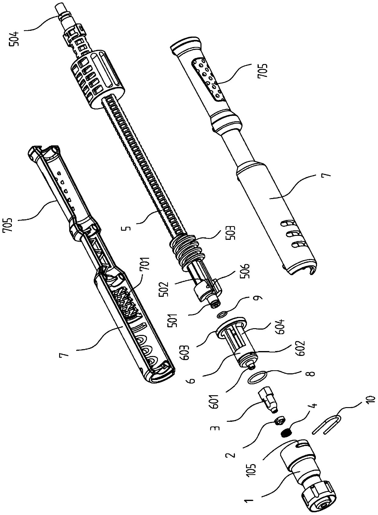
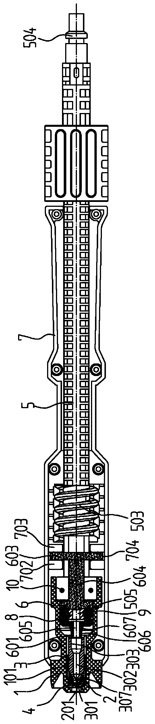
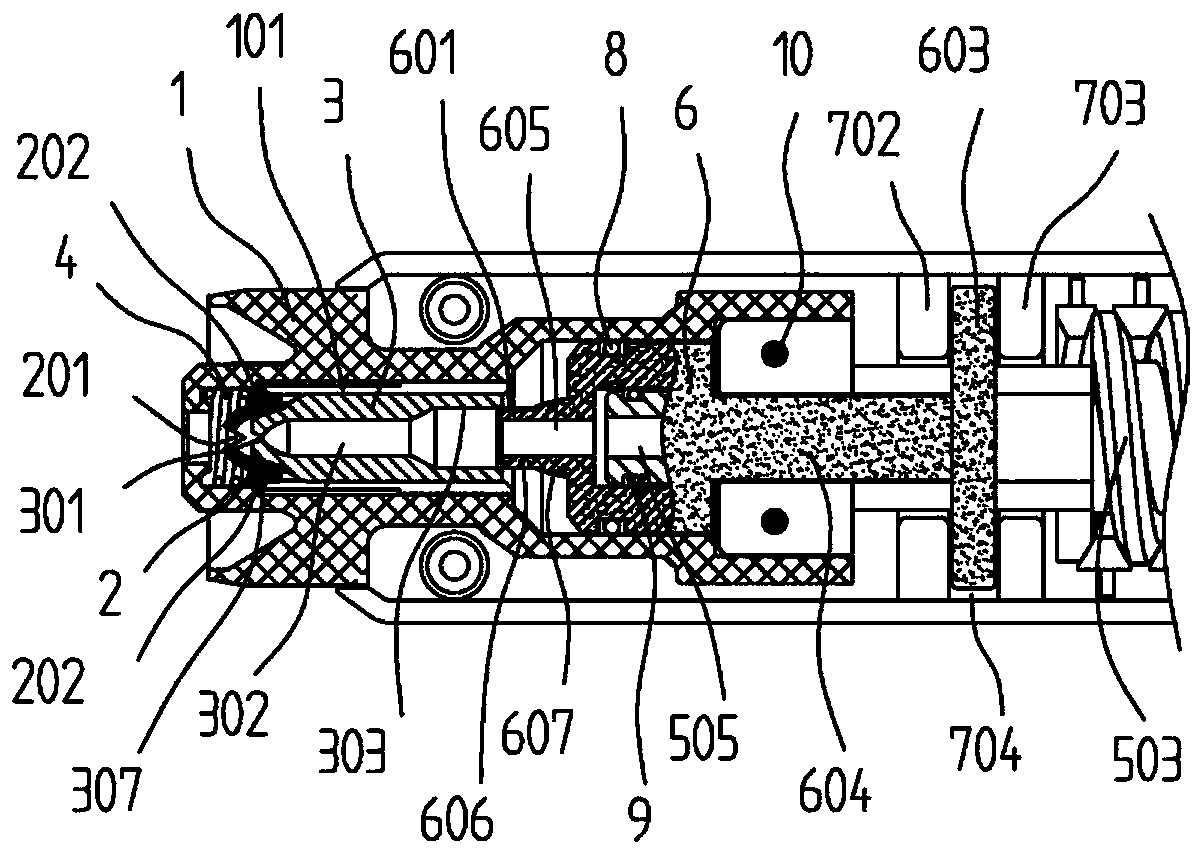
[0053] Such as Figures 1 to 7 As shown, a high-pressure cleaning device can prevent dripping at the outlet. The way to achieve this goal is to use an anti-drip high and low pressure combined nozzle. Valve 6, which has a water hole 605, head shell 1, which has a cavity through its front and rear ends to accommodate the high-pressure nozzle 3 and the slide valve 6; low-pressure nozzle 2, which has a center facing all The main water outlet 201 of the central spray channel 302 , at least one auxiliary water outlet 202 arranged around the main water outlet 201 , and the spring 4 . The slide valve 6 is slidably arranged behind the high-pressure nozzle 3; the outer wall of the slide valve 6 forms a sliding seal with the wall of the cavity, and the outer wall of the high-pressure nozzle 3 and the wall of the cavity A bypass path 101 is formed between the walls of the cavity, and the bypass path 101 can communicate with or be closed to the central nozzle 302 when the sliding valve 6 ...

Embodiment 2

[0068] Such as Figure 16 As shown, the difference from Embodiment 1 is that in this embodiment, as another typical linear adjustment structure, the discharge groove 601 extends along a helix, and the central axis of the helix is ​​parallel to the outer cylindrical surface 606. central axis. In addition to Embodiment 1 and this embodiment, the discharge groove 601 can also adopt other structures, such as oblique, but due to the consideration of manufacturing cost and difficulty, the discharge in Embodiment 1 and this embodiment is given priority. Structure of groove 601.

[0069] The present invention discloses a high-pressure cleaning equipment using combined nozzles, but other working devices except the nozzles have been disclosed in the prior art. The present invention only improves the nozzles, so the disclosure of the technical solution is comprehensive ground and clearly.


PUM


Abstract

The invention discloses an anti-dripping high-low-pressure combined nozzle and high-pressure cleaning equipment. The anti-dripping high-low-pressure combined nozzle comprises a high-pressure nozzle body, a sliding valve, a head shell, a low-pressure nozzle body and a spring. The high-pressure nozzle body is provided with a center spray channel. The sliding valve is provided with a water hole. Thehead shell is provided with a cavity penetrating the front end and the rear end of the head shell and being used for containing the high-pressure nozzle body and the sliding valve. The low-pressure nozzle body is provided with a main water outlet and at least one auxiliary water outlet formed in the peripheral side of the main water outlet. The sliding valve is slidably arranged on the rear portion of the high-pressure nozzle body. Sliding sealing is formed between the outer wall of the sliding valve and the cavity wall of the cavity. A bypass path is formed between the outer wall of the high-pressure nozzle body and the cavity wall of the cavity. The low-pressure nozzle body is slidably arranged in the cavity of the head shell and in sliding sealing fit with the head shell. The low-pressure nozzle body is located in the front of the high-pressure nozzle body. The spring is located in the cavity of the head shell and abuts against the low-pressure nozzle body and the head shell. The low-pressure nozzle body can be in contact with the high-pressure nozzle body to form sealing. The auxiliary water outlets communicate with the bypass path. The anti-dripping high-low-pressure combinednozzle has the beneficial effect that the dripping phenomenon of the water outlets can be improved effectively and eliminated.

Description

technical field [0001] The invention belongs to the technical field of cleaning equipment, and in particular relates to an anti-drip high and low pressure combined nozzle and high-pressure cleaning equipment. Background technique [0002] High-pressure cleaning equipment is a kind of equipment that uses water or a mixed solution added with cleaning agent as the cleaning medium, and uses high-pressure water flow to clean the surface of the object. It is mainly composed of a spray gun unit and a motor pump unit. The spray gun unit is responsible for forming different shapes according to actual needs. water flow, while the motor-pump unit delivers the water from the municipal water mains to the spray gun unit. [0003] Nozzles / sprinklers are the executive elements in high-pressure water cleaning equipment. The principle is to use the change of the inner hole area of ​​the nozzles / sprinklers to gather high-pressure water, convert it into kinetic energy and then spray it out in t...

Claims


Application Information

Patent Timeline
Patent Type & Authority Patents(China)
IPC IPC(8): B05B1/30B05B1/16
Inventor 林有余刘楷
Owner SUMEC HARDWARE & TOOLS
Why Eureka
Try Eureka