


Quick Research
Generate reliable direction feasibility study reports for your R&D in just a few steps.

Technical Q&A
Discover and master advanced knowledge NOW. Basics, ideas, possibilities, all at once.

Find Solutions
As an expert in R&D theories, this can generate solutions to your technical problems instantly.

Evaluate Feasibility
Analyze your overall solution with one click, know your potential R&D risks in advance.

Monitor Landscape
Get weekly tech updates, stay abreast of the latest tech innovations and key insights.
Directional grounding wire clamping head
A technology of grounding wire and directional wire, which is applied in the direction of electrical connection sockets, etc., can solve the problems that it is difficult for the clamp of the grounding wire to clamp the wire, accelerate the loss of the tail rope and the clamp, and the efficiency is not high, so as to improve the hanging efficiency and reduce the Probability of collision, effect of increasing fixed effects
- Summary
- Abstract
- Description
- Claims
- Application Information
AI Technical Summary
Problems solved by technology
Method used
Image

Examples
Embodiment 1
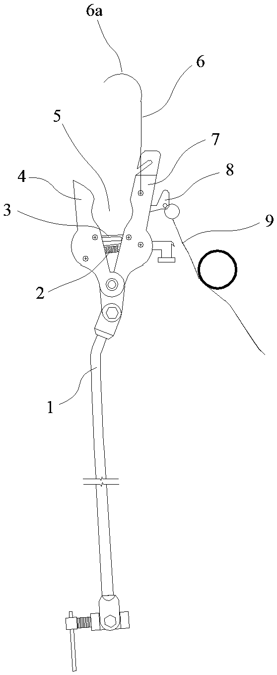
[0020] Such as figure 1 In the illustrated embodiment, a directional ground wire clamp includes a first clamping plate 7, a second clamping plate 4 and a handle 1, and the bottoms of the first clamping plate and the second clamping plate are rotatably connected On the handle, an upward opening 5 is provided between the first clamping plate and the second clamping plate, and a movable push rod 3 and a collet spring 2 are arranged in the opening, and the collet spring is used to hold the first clamping plate and the second clamping plate are tensioned, and the movable ejector rod is used for positioning the first clamping plate and the second clamping plate. A deadbolt is also provided in the opening. When the wire enters the bottom of the opening, the wire contacts the deadbolt, and the deadbolt drives the movable push rod to release the positioning of the first clamping plate and the second clamping plate. The first clamping plate is provided with an orientation line 6 extend...
Embodiment 2
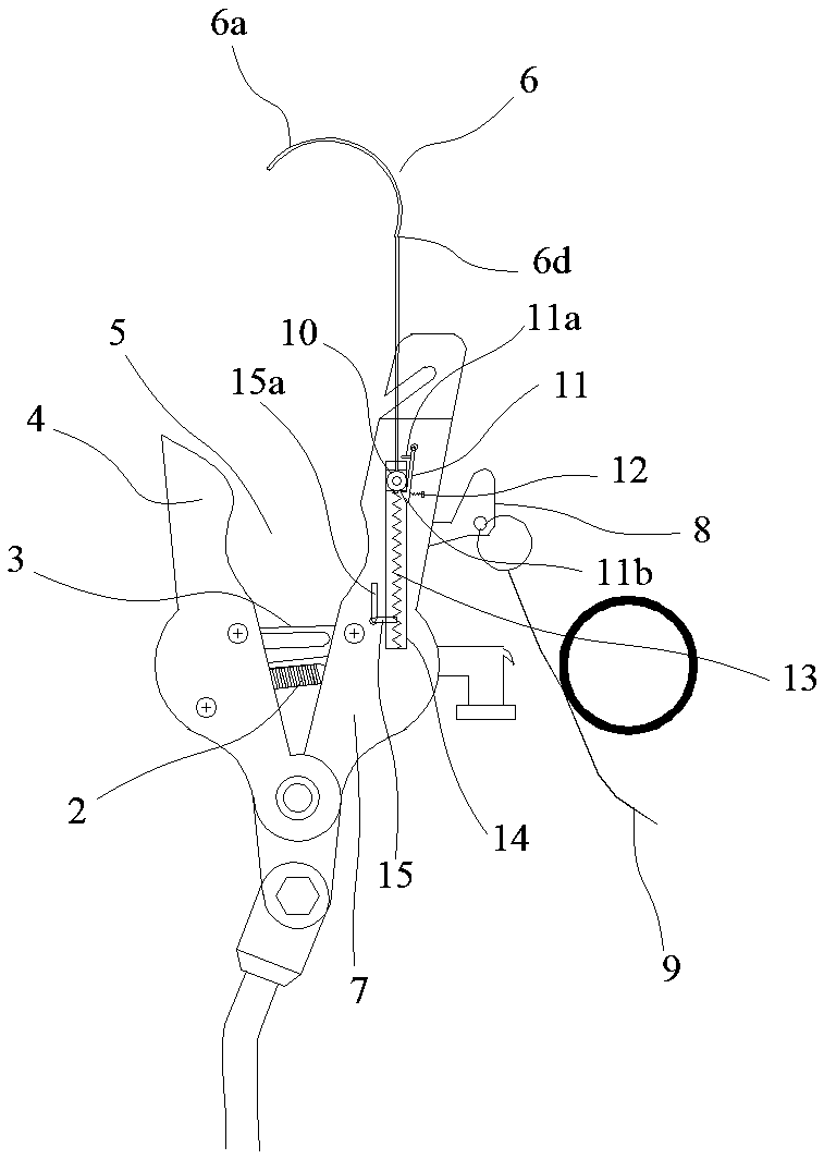
[0024] Such as image 3 In the illustrated embodiment, a directional ground wire clamp includes a first clamping plate 7, a second clamping plate 4 and a handle 1, and the bottoms of the first clamping plate and the second clamping plate are rotatably connected On the handle, an upward opening 5 is provided between the first clamping plate and the second clamping plate, and a movable push rod 3 and a collet spring 2 are arranged in the opening, and the collet spring is used to hold the first clamping plate and the second clamping plate are tensioned, and the movable ejector rod is used for positioning the first clamping plate and the second clamping plate. A deadbolt is also provided in the opening. When the wire enters the bottom of the opening, the wire contacts the deadbolt, and the deadbolt drives the movable push rod to release the positioning of the first clamping plate and the second clamping plate. The first clamping plate is provided with an orientation line 6 extend...
PUM
 Abstract
Description
Claims
Application Information
 - R&D Engineer
- R&D Manager
- IP Professional
- Industry Leading Data Capabilities
- Powerful AI technology
- Patent DNA Extraction
Browse by: Latest US Patents, China's latest patents, Technical Efficacy Thesaurus, Application Domain, Technology Topic, Popular Technical Reports.
© 2024 PatSnap. All rights reserved.Legal|Privacy policy|Modern Slavery Act Transparency Statement|Sitemap|About US| Contact US: help@patsnap.com