Handheld slit lamp microscope
A slit lamp microscope, handheld technology, applied in ophthalmoscope, medical science, eye testing equipment, etc., can solve the problems of short distance, observation optical system can not be continuously zoomed, can not zoom, etc.
- Summary
- Abstract
- Description
- Claims
- Application Information
AI Technical Summary
Problems solved by technology
Method used
Image

Examples
Embodiment 1
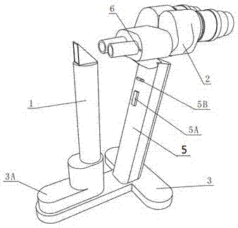
[0030] Embodiment one, such as figure 1 and figure 2 Shown is the external view of this embodiment, as the external view of the handheld slit lamp microscope of the present invention.
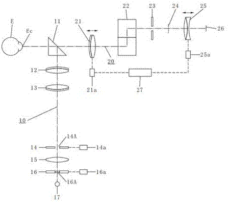
[0031] It can be seen that the hand-held slit lamp microscope of this embodiment includes an illumination device 1, an observation device 2, and a base 3. The illumination device 1 is a cylinder installed on the base 3, and an illumination optical system 10 is arranged in the cylinder as an illumination device. The cylinder and the base 3 are vertically arranged, the reflective prism 11 in the illumination optical system 10 is arranged on the top of the cylinder, the observation device 2 is installed on the base 3 through the handle 5, the light beam of the illumination device 1 and the observation device 2 The observation optical path is vertical, and two symmetrical observation optical systems 20 are arranged on the observation device 2 to facilitate observation by two eyes.
[0032] In ad...
Embodiment 2
[0061] In this embodiment, on the basis of the first embodiment, the linkage mechanism 27 and the drive unit 25a are omitted.
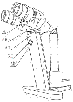
[0062] After controlling the objective lens drive unit 21a by using the zoom lever 5F to control and drive the objective lens 21 to move forward and backward in the direction of the optical axis of the observation optical path, manually move the eyepiece 25 to an appropriate position.
[0063] The proper position of the above-mentioned eyepiece 25 is that the distance between the eyepiece 25 and the cornea Ec of the subject's eye E is [S o +F 21 *S o / (S o -F 21 )+F 25 ] at.
[0064] In addition, the eyepiece diaphragm 23 is connected with the eyepiece 25 and moves together.
Embodiment 3
[0066] In this embodiment, on the basis of the first embodiment, the interlocking mechanism 27 and the eyepiece driving unit 25 a are canceled, and the eyepiece 25 is fixed to the observation device 2 . An unillustrated two-position sliding structure is added to the base 3, the lighting device 1 is fixed to the front section of the base 3, and the observation device 2 is fixed to the rear section of the base 3. The above-mentioned two-stage position sliding structure can make the illuminating device 1 and the observation device 2 move relative to each other in two stages.
[0067] After controlling the objective lens drive unit 21a by using the zoom lever 5F to drive the objective lens 21 to advance and retreat in the direction of the optical axis of the observation optical path, manually move the observation device 2 to a proper position.
[0068] The appropriate position of the observation device 2 is that the distance between the eyepiece 25 and the cornea Ec of the subject...
PUM
 Abstract
Description
Claims
Application Information
 - R&D
- Intellectual Property
- Life Sciences
- Materials
- Tech Scout
- Unparalleled Data Quality
- Higher Quality Content
- 60% Fewer Hallucinations
Browse by: Latest US Patents, China's latest patents, Technical Efficacy Thesaurus, Application Domain, Technology Topic, Popular Technical Reports.
© 2025 PatSnap. All rights reserved.Legal|Privacy policy|Modern Slavery Act Transparency Statement|Sitemap|About US| Contact US: help@patsnap.com