
Backflow cable anti-theft alarm system

An anti-theft alarm and return cable technology, which is applied in the direction of mechanical start of anti-theft alarm, alarms by breaking/disturbing the straightened rope/metal wire, etc., can solve the problem of theft of return cables

Pending Publication Date: 2018-04-03
HANGZHOU POWER SUPPLY COMPANY OF STATE GRID ZHENGJIANG ELECTRIC POWER +2
View PDF6 Cites 6 Cited by
  • Summary
  • Abstract
  • Description
  • Claims
  • Application Information

AI Technical Summary

Problems solved by technology

[0003] The present invention aims to provide a backflow cable anti-theft alarm system, which will give an alarm when the backflow cable is stolen, so as to solve the problem of the backflow cable being stolen in the prior art solution

Method used


Image

  • Backflow cable anti-theft alarm system
  • Backflow cable anti-theft alarm system
  • Backflow cable anti-theft alarm system

Examples


Embodiment 1

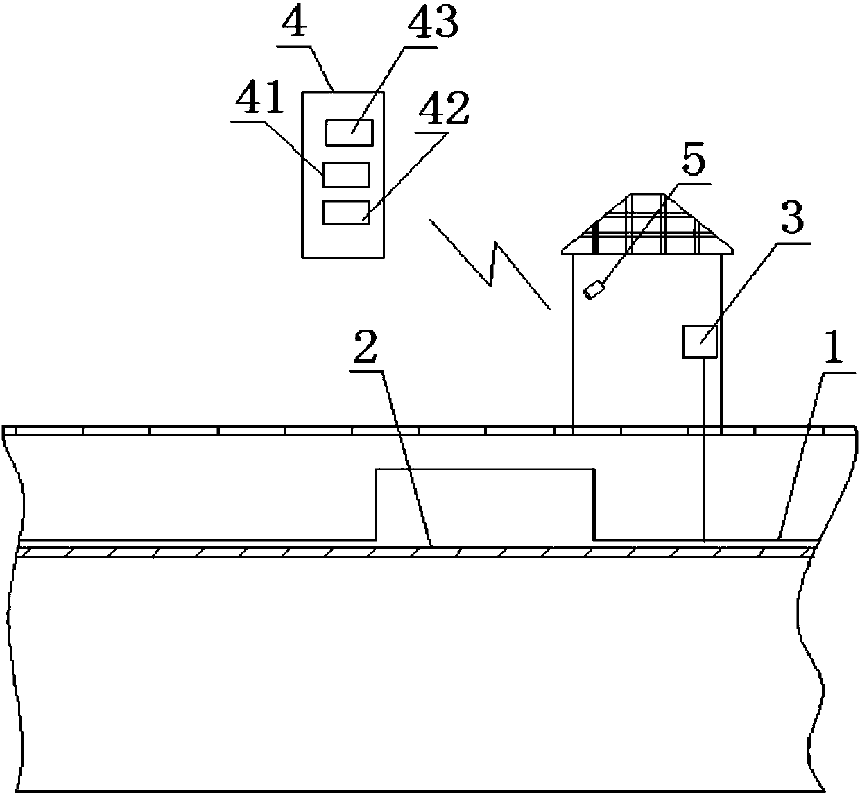
[0034] Such as figure 1 As shown, the present invention provides backflow cable anti-theft alarm system, comprising:

[0035] The first vibration optical cable 1 is laid at the return cable for collecting the first vibration signal of the return cable 2;

[0036] The first data collector 3 is connected with the first vibration optical cable 1, and is used to obtain the first vibration signal collected by the first vibration optical cable 1, and transmit the first vibration signal to the first optical fiber vibration early warning host 4;

[0037] The first optical fiber vibration early warning host 4, the first optical fiber vibration early warning host 4 is provided with a first acquisition unit 41 and a first processing unit 42;

[0038] The first acquisition unit 41 is used to acquire the first vibration signal transmitted by the first data collector 3;

[0039] The first processing unit 42 is used to judge whether the return cable 2 is stolen according to the first vibra...

Embodiment 2

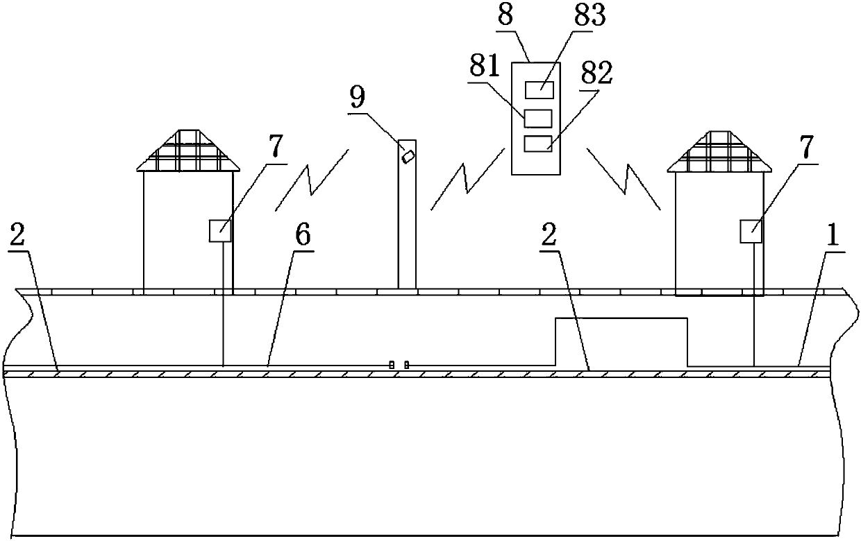
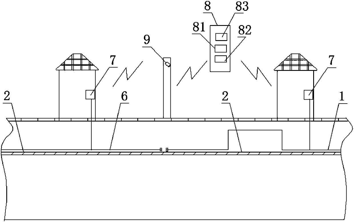
[0046] Such as figure 2 and image 3 As shown, the present invention discloses another backflow cable anti-theft alarm system, comprising:

[0047] Several second vibrating optical cables 6, the second vibrating optical cables 6 are arranged sequentially in the direction of the return cable 2, and are used to collect the second vibration signal of the return cable 2 section;

[0048] Several second data collectors 7, the second data collectors 7 are connected to the second vibration optical cable 6 in one-to-one correspondence, and are used to obtain the second vibration signal collected by the second vibration optical cable 6 connected thereto; The data collector 7 sends the second vibration signal and the unique identification of the second data collector 7 to the second optical fiber vibration early warning host computer 8;

[0049] Some rotatable second cameras 9, the second cameras 9 are arranged above the ground plane, for photographing the area where the return cable...

Embodiment approach

[0061] As a preferred implementation manner: the model of the second camera 9 is DS-2CD3Q10FD-IW.


PUM


Abstract

The invention aims to provide a backflow cable anti-theft alarm system. Alarm is reported when the backflow cable is stolen, thus problem of stealing the backflow cable in the prior art is solved. A first vibrating cable is paved at the backflow cable and used for collecting a first vibration signal of the backflow cable; a first data collector is used for acquiring the first vibration signal collected by the first vibrating cable and transmitting the first vibration signal to a first fiber vibration early warning host machine; the first fiber vibration early warning host machine is provided with a first acquiring unit and a first processing unit; the first acquiring unit is used for acquiring first vibration signal transmitted by a first data collector, and the first processing unit is used for judging if the backflow cable is stolen according to the first vibration signal acquired by the first acquiring unit, and alarming according to the judging result. The system can automaticallyjudge if the backflow cable is stolen; when the backflow cable is stolen, the system reports an alarm, and thus workers can timely prevent the backflow cable from being stolen.

Description

technical field [0001] The invention relates to the field of electric power, in particular to a backflow cable anti-theft alarm system. Background technique [0002] The development of transmission cables in the past ten years can be described as leaps and bounds. No matter in terms of the scale of power facilities or the reliability of power supply quality, great achievements have been made. At the same time, transmission cables have also caused a lot of equipment theft. Among them, the cable return cable is the most representative, which directly poses a threat to the safe and stable operation of the power grid system. As cable managers, it is our duty to combat the crime of theft or vandalism of cable facilities, which endangers the security of the grid. Therefore, it is urgent to prevent the return cable from being stolen. Therefore, it is necessary to design a backflow cable anti-theft alarm system to prevent the backflow cable from being stolen. Contents of the in...

Claims


Application Information

Patent Timeline
Patent Type & Authority Applications(China)
IPC IPC(8): G08B13/12
CPCG08B13/12
Inventor 黄肖为吴健儿赵明娄雨风池俊锋倪晓璐孟庆铭董琪杨先进洪晓东张开成李富平姚广元
Owner HANGZHOU POWER SUPPLY COMPANY OF STATE GRID ZHENGJIANG ELECTRIC POWER
Learn More