Anchored type arch bridge suspender system combining flexible inhaul cable with rigid pull rod

A technology of flexible cables and suspenders, which is applied in the field of arch bridge components, can solve problems such as horizontal stress, centering error, new suspenders, and limited conduit expansion, and achieve the effect of structural solution and convenient maintenance and inspection

Pending Publication Date: 2018-03-30
GUANGDONG HELI CIVIL ENG CO LTD +1
View PDF0 Cites 4 Cited by
  • Summary
  • Abstract
  • Description
  • Claims
  • Application Information

AI Technical Summary

Problems solved by technology

[0011] The object of the present invention is to provide an anchored arch bridge suspender system with a flexible cable combined with a rigid tie rod. The adjustment of the boom force also solves the problem of the horizontal stress on the new boom caused by the centering error of the upper and lower pre-buried pipe holes caused by the deformation of the arch rib or the external force of the beam during the construction of the new bridge or during the operation process
[0013] The boom system of the present invention is a composite boom combined with rigid pull rods and flexible cables. The boom system is adjustable, inspectable and replaceable, which not only facilitates later maintenance inspection, replacement, and boom force adjustment, but also solves the During the construction or operation process, the deformation of the arch rib or the external force of the beam will lead to the centering error of the upper and lower pre-embedded pipe holes, which will cause horizontal stress on the new suspender. Constraints on beam position and arch bridge tie rod position lead to the problem of limited reaming of upper and lower conduits

Method used


Image

  • Anchored type arch bridge suspender system combining flexible inhaul cable with rigid pull rod
  • Anchored type arch bridge suspender system combining flexible inhaul cable with rigid pull rod
  • Anchored type arch bridge suspender system combining flexible inhaul cable with rigid pull rod

Examples


Embodiment Construction

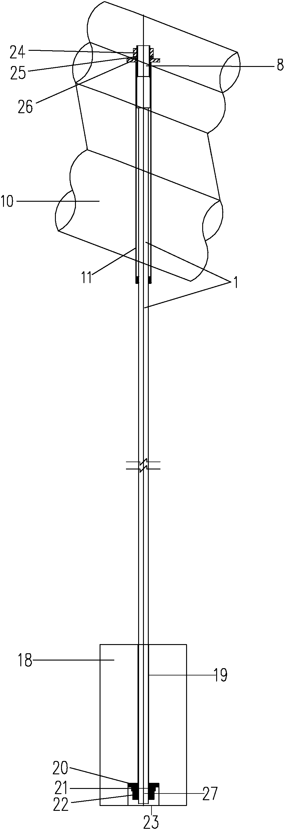
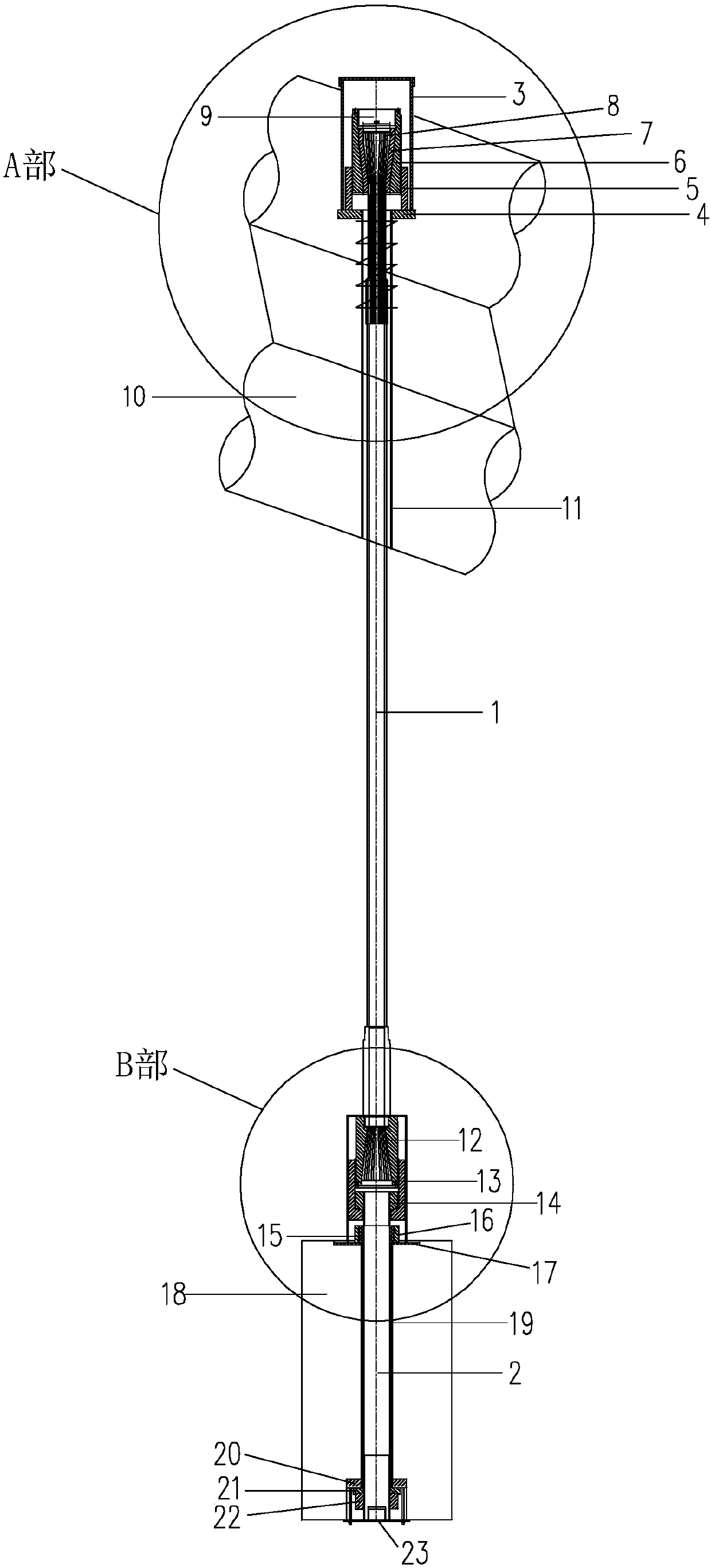
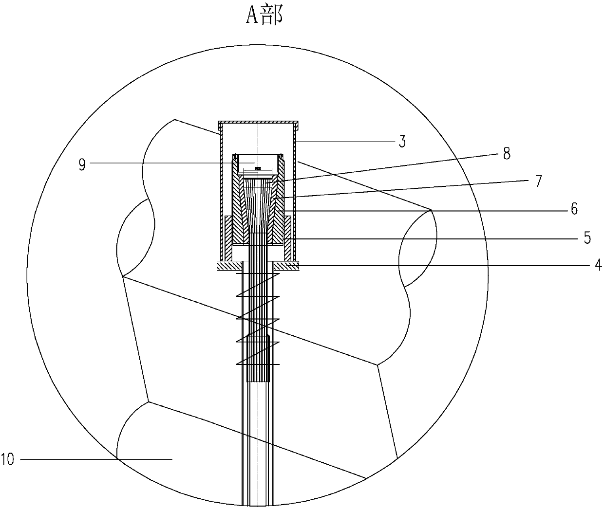
[0051] The anchored arch bridge suspender system of flexible stay cable of the present invention combined with rigid pull rod is as Figure 2 to Figure 8 As shown, it includes an upper anchor head, an upper anchor member, a suspender cable body 1, a steel tie rod 2, a lower anchor head and a lower anchor member. In the hole, an arch rib pre-embedded pipe 11 is pre-buried in the arch rib 10, and the upper end of the suspender cable body 1 is the upper anchor head. The suspender cable body 1 is anchored in the arch rib, and the steel tie rod 2 is a rigid tie rod. The lower end of the suspender cable body 1 and the upper end of the steel tie rod 2 are connected by a cable rod connecting member, and the lower anchor member is located in the anchor hole of the arch bridge beam 18 , the crossbeam 18 is pre-embedded with a crossbeam pre-embedded pipe 19, the lower end of the steel tie rod 2 is the lower anchor head, the lower anchor head passes through the crossbeam pre-embedded pipe...


PUM


Abstract

The invention discloses an anchored type arch bridge suspender system combining a flexible inhaul cable with a rigid pull rod. The suspender system comprises a suspender cable body, an upper anchor head, an upper anchoring component, a steel pull rod, a lower anchor head and a lower anchoring component. The suspender cable body is the flexible inhaul cable. The upper anchoring component is locatedin an anchoring hole of an arch rib of an arch bridge. An arch rib embedded pipe is embedded in the arch rib. The upper end of the suspender cable body is the upper anchor head. The upper anchor headpenetrates through the arch rib embedded pipe and then is connected with the upper anchoring component. The steel pull rod is the rigid pull rod. The lower end of the suspender cable body is connected with the upper end of the steel pull rod through a cable and rod connecting component. The lower anchoring component is located in an anchoring hole of a crossbeam of the arch bridge. A crossbeam embedded pipe is embedded in the crossbeam. The lower end of the steel pull rod is the lower anchor head. The lower anchor head penetrates through the crossbeam embedded pipe and then is connected withthe lower anchoring component. The suspender system adopts the combination of the flexible inhaul cable and the rigid pull rod and can be adjusted, inspected and replaced.

Description

technical field [0001] The invention relates to an arch bridge component, in particular to an anchored arch bridge suspender system in which flexible cables are combined with rigid pull rods. Background technique [0002] At present, the common structure of the arch bridge suspender system in the prior art is as follows: figure 1 As shown, an upper anchoring unit is pre-embedded in the arch rib 10 of the arch bridge, and the upper anchoring unit includes an upper spherical nut 24, an upper spherical bearing 25 and an upper anchor pad 26 arranged from top to bottom and surrounding the upper anchor head 8, The spherical nut 24 is connected with the upper anchor head 8 of the suspender with external threads, so as to transmit the force of the suspender cable body 1 to the arch rib 10, and the upper anchor unit is poured with concrete after the construction is completed to form an integral body with the arch rib 10; 10 has an upper pre-embedded pipe 11 arranged vertically. The ...

Claims


Application Information

Patent Timeline
IPC IPC(8): E01D4/00E01D19/00E01D19/14
CPCE01D4/00E01D19/00E01D19/14
Inventor 杨文甫熊杰张长利肖开军罗小聪李鸿彬戴春洋
Owner GUANGDONG HELI CIVIL ENG CO LTD
Why Eureka
Try Eureka