
Battery cell getting-into-shell separating and spacing device

A battery cell and separation technology, applied in the direction of transportation and packaging, conveyor objects, etc., can solve the problems of hidden dangers in stability, increase of unstable factors, uncontrollable free state, etc., and achieve simple and convenient separation process, mechanism streamlined effect

Pending Publication Date: 2018-03-30
常州华数锦明智能装备技术研究院有限公司
View PDF0 Cites 14 Cited by
  • Summary
  • Abstract
  • Description
  • Claims
  • Application Information

AI Technical Summary

Problems solved by technology

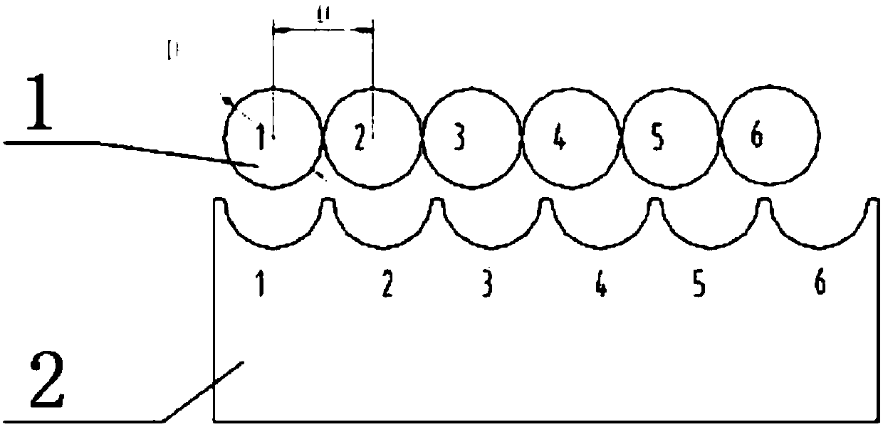
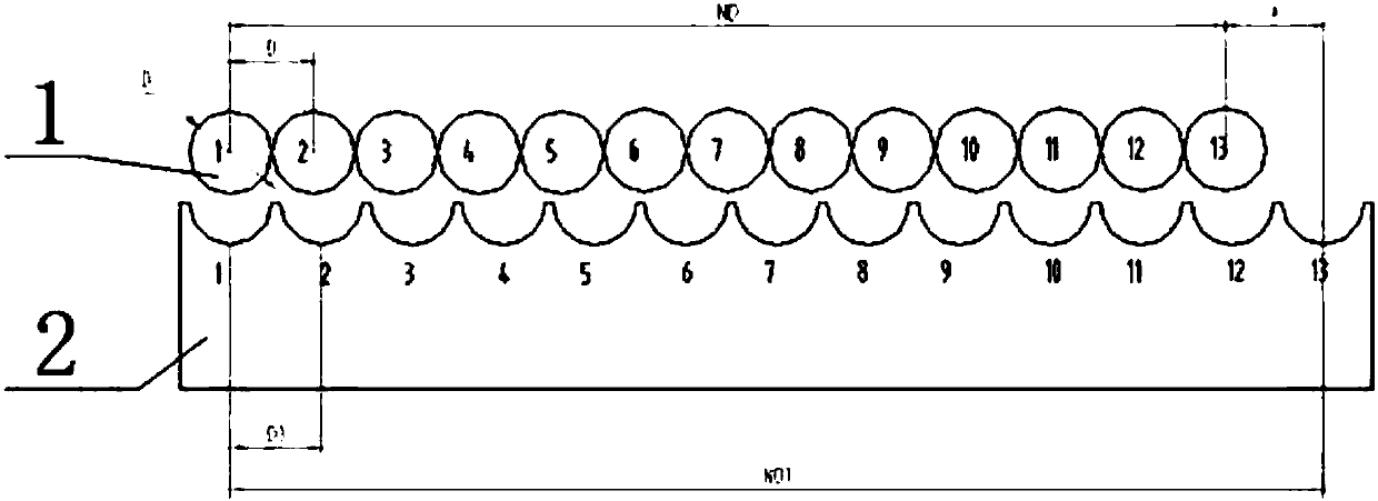
[0005] Suppose D,D 1 Definitely, the difference between the batteries arranged before and after the spacing is △=N·D 1 -N·D, it can be found that with the increase of the number of cells N, the difference △ will become larger and larger, and when the difference △ accumulates to a certain value, the cells will not be able to accurately roll into the fixed distance block
[0006] Assuming that D and N are fixed, the difference between the batteries arranged before and after the separation distance is △=N·D 1 -N·D, it can be found that the distance between the center of the battery cell and the value D 1 As the value increases, the difference △ will become larger and larger. When the difference △ accumulates to a certain value, the battery will not be able to accurately roll into the fixed distance block
[0007] Due to the free rolling by the gravity of the battery cell, the attitude of the battery cell in the rolling process is in a free state and cannot be controlled, and there are hidden dangers in the stability. With the increase of the number of battery cells, the instability factors increase

Method used


Image

  • Battery cell getting-into-shell separating and spacing device
  • Battery cell getting-into-shell separating and spacing device
  • Battery cell getting-into-shell separating and spacing device

Examples


Embodiment 1

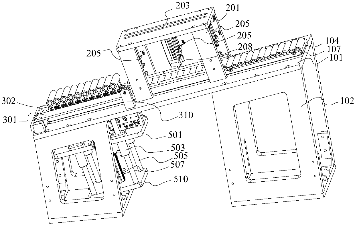
[0047] see image 3 As shown, the present invention provides a device for distributing and separating cells into the shell, including: a support frame body, a cell raceway 104 arranged on the support frame body, a material distribution mechanism, a material blocking mechanism, and a jacking and separation distance mechanism.

[0048] The support frame body includes an inclined slope 101 and support frames 102 respectively arranged at the bottom of the high end and the bottom of the low end of the slope 101 .

[0049] The cell raceway 104 is adapted to be assembled on the slope surface 101 of the supporting frame body, and a hollow groove 105 is provided on the part of the cell raceway 104 corresponding to the support frame 102 on the lower end surface.

[0050] Preferably, the battery raceway 104 is provided with a raceway baffle 107 adapted to change the width of the battery raceway 104 along one side edge of the battery raceway 104 in the length direction.

[0051]The mate...


PUM


Abstract

The invention relates to the technical field of manufacturing of lithium batteries, in particular to a battery cell getting-into-shell separating and spacing device. The battery cell getting-into-shell separating and spacing device comprises a supporting frame body, a battery cell roller path, a material separating mechanism, a material blocking mechanism and a jacking spacing mechanism, wherein the supporting frame body comprises an inclined slope surface and supporting frames respectively arranged at the bottoms of the high-end surface and the low-end surface of the slope surface; the battery cell roller path is suitable for being assembled on the slope surface of the supporting frame body; an empty slot is formed in a position, which corresponds to the supporting frame on the low-end surface, on the battery cell roller path; the material separating mechanism comprises a U-shaped bracket arranged in a region, which is located between the high-end surface and the low-end surface, at the top of the slope surface; the material blocking mechanism is arranged on the empty slot in the top of the slope surface, and comprises a cover plate covering or exposing the empty slot; and the jacking spacing mechanism comprises a battery cell loading part extending out of the empty slot, a jacking assembly for jacking the battery cell loading part, and a spacing assembly for spacing a plurality of battery cell loading positions of the battery cell loading part. The battery cell getting-into-shell separating and spacing device disclosed by the invention can integrally solve the problems onseparation and spacing of battery cells.

Description

technical field [0001] The invention relates to the technical field of lithium battery manufacturing, in particular, to a device for distributing materials and distances for batteries inserted into shells. Background technique [0002] At this stage, when the battery cells come into the shell, they are a fixed number of incoming materials, which is not convenient for quick change and adjustment, and an additional material sorting mechanism is required to place the cells on the material distribution mechanism, which increases costs and cannot buffer redundant cells. The action beat time increases, and the action efficiency is low. [0003] see figure 1 As shown, the current state of incoming batteries is that they are placed closely together one by one. The distance between the cells adopts a fixed distance block. Make the cell roll into the groove to realize the separation of the cell. [0004] see figure 2 As shown, the diameter of the cell is D, the radius is , the nu...

Claims


Application Information

Patent Timeline
Patent Type & Authority Applications(China)
IPC IPC(8): B65G47/26B65G47/82
CPCB65G47/26B65G47/261B65G47/82
Inventor 申灿邓少武钱栋梁王玉宝吴岩
Owner 常州华数锦明智能装备技术研究院有限公司
Learn More