Controllable finger capable of being bent in multiple directions

A finger and bending direction technology, applied in the field of controllable fingers, can solve the problems of complex maintenance, short service life and high cost, and achieve the effects of simple maintenance, long service life and simple production

Pending Publication Date: 2018-03-30
GUIZHOU UNIV
View PDF4 Cites 1 Cited by
  • Summary
  • Abstract
  • Description
  • Claims
  • Application Information

AI Technical Summary

Problems solved by technology

[0002] At present, human fingers or existing mechanical fingers can only be bent and straightened to achieve some traditional human-like functions. In the process of continuous development, the existing technology is no longer practical, and it is necessary to break the traditional concepts of people. Fingers, especially the rapid development of intelligence, require fingers with more functions, which can be flexed and stretched in multiple directions at the same time to complete functions in different directions; and for existing mechanical fingers, the manufacturing process is complicated and the cost is high. Due to the characteristics of short service life, complicated maintenance and poor practicability, a controllable multi-directional bending finger has been developed to solve the above problems.
[0003] To sum up, in the prior art, mechanical fingers also have technical problems such as complex manufacturing process, high cost, short service life, complicated maintenance, human fingers or existing mechanical fingers can only be bent and straightened, and poor practicability

Method used


Image

  • Controllable finger capable of being bent in multiple directions
  • Controllable finger capable of being bent in multiple directions
  • Controllable finger capable of being bent in multiple directions

Examples


Embodiment Construction

[0015] The present invention will be further described below in conjunction with the accompanying drawings and embodiments, but not as a basis for limiting the present invention.

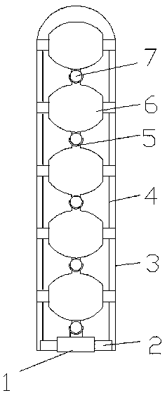
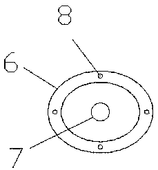
[0016] Example. A finger with controllable bending direction, constituted as Figure 1-4 As shown, it includes a group of gyro unit sections 6. A spherical joint 7 is provided at the axis of the lower end of the gyro unit section 6, and an arc-shaped connecting sleeve 5 is provided at the other end. The spherical joint 7 between adjacent gyro unit sections 6 Set in the arc-shaped connecting sleeve 5, the spherical connecting joint 7 at the lower end of the bottommost gyro unit section 6 is arranged in the arc-shaped connecting sleeve 5, the arc-shaped connecting sleeve 5 is connected to the fixed end 1, and the topmost gyro unit section 6 The upper end surface is arc-shaped, and the lower end is provided with the spherical joint 7; four traction holes 8 are evenly distributed around the gyro unit s...


PUM


Abstract

The invention discloses a controllable finger capable of being bent in multiple directions. The controllable finger comprises a set of gyroscope unit sections. Spherical linkage sections are arrangedat the axis positions of the lower ends of the gyroscope unit sections, and arc-shaped connecting sleeves are arranged at the other ends of the gyroscope unit sections. The spherical linkage sectionsbetween the adjacent gyroscope unit sections are arranged inside the corresponding arc-shaped connecting sleeves. The spherical linkage section at the lower end of the gyroscope unit section on the bottommost portion is arranged in the corresponding arc-shaped connecting sleeve, and the arc-shaped connecting sleeve is connected to a fixed end. The upper end face of the gyroscope unit section at the topmost end is in an arc shape, and the lower end of the gyroscope unit section is provided with the corresponding spherical linkage section. Four traction holes are evenly distributed in the periphery of each gyroscope unit section. The traction holes of the set of the gyroscope unit sections in the same direction are internally provided with pulling ropes separately, and the lower ends of thefour pulling ropes are connected with a micro motor. The controllable finger capable of being bent in the multiple directions has the beneficial effects that manufacturing is simple, cost is low, theservice life is long, repair and maintenance are easy, controllable bending and stretching in the four directions can be achieved and the practicability is good.

Description

technical field [0001] The invention relates to a controllable finger, in particular to a controllable multi-directional bending finger. Background technique [0002] At present, human fingers or existing mechanical fingers can only be bent and straightened to achieve some traditional human-like functions. In the process of continuous development, the existing technology is no longer practical, and it is necessary to break the traditional concepts of people. Fingers, especially the rapid development of intelligence, require fingers with more functions, which can be flexed and stretched in multiple directions at the same time to complete functions in different directions; and for existing mechanical fingers, the manufacturing process is complicated and the cost is high. Short service life, complex maintenance, and poor practicability, a controllable multi-directional bending finger was developed to solve the above problems. [0003] To sum up, in the prior art, mechanical fi...

Claims


Application Information

Patent Timeline
IPC IPC(8): B25J9/10B25J9/06B25J17/02
CPCB25J9/06B25J9/104B25J17/0275
Inventor 任三三
Owner GUIZHOU UNIV
Why Eureka
Try Eureka