
Diameter detection mechanism for shaft-class parts

A technology for detecting mechanisms and shaft parts, which is applied in the direction of measuring devices, conveyor objects, instruments, etc., can solve the problems of insufficient stability of detection data, low detection accuracy, and affecting processing efficiency, etc., to achieve easy maintenance and repair, detection accuracy High and reduce the effect of labor cost

Inactive Publication Date: 2018-03-16
DALIAN DEMAISHI PRECISION TECH CO LTD
View PDF4 Cites 4 Cited by
  • Summary
  • Abstract
  • Description
  • Claims
  • Application Information

AI Technical Summary

Problems solved by technology

[0002] Shaft parts are very common parts in the machinery industry, and they are also very important parts. The shape error accuracy directly affects the motion performance and service life of the machine. With the development of the machinery industry, the requirements for shafts are getting higher and higher. When detecting the diameter of parts, the traditional detection is to use pure artificial vision detection or the combination of artificial vision with mechanical measuring tools and optical instruments. Manual detection often has disadvantages such as low efficiency, poor reliability, low detection accuracy, and high cost; using Industrial camera detection, the detection accuracy is not high, the detection data is not stable enough, and it is greatly affected by external light; neither manual nor industrial camera detection can realize automatic detection on the production line, and the parts need to be installed manually, which seriously affects the processing efficiency

Method used


Image

  • Diameter detection mechanism for shaft-class parts
  • Diameter detection mechanism for shaft-class parts
  • Diameter detection mechanism for shaft-class parts

Examples


Embodiment Construction

[0016] Next, the present invention will be described in detail in conjunction with the accompanying drawings

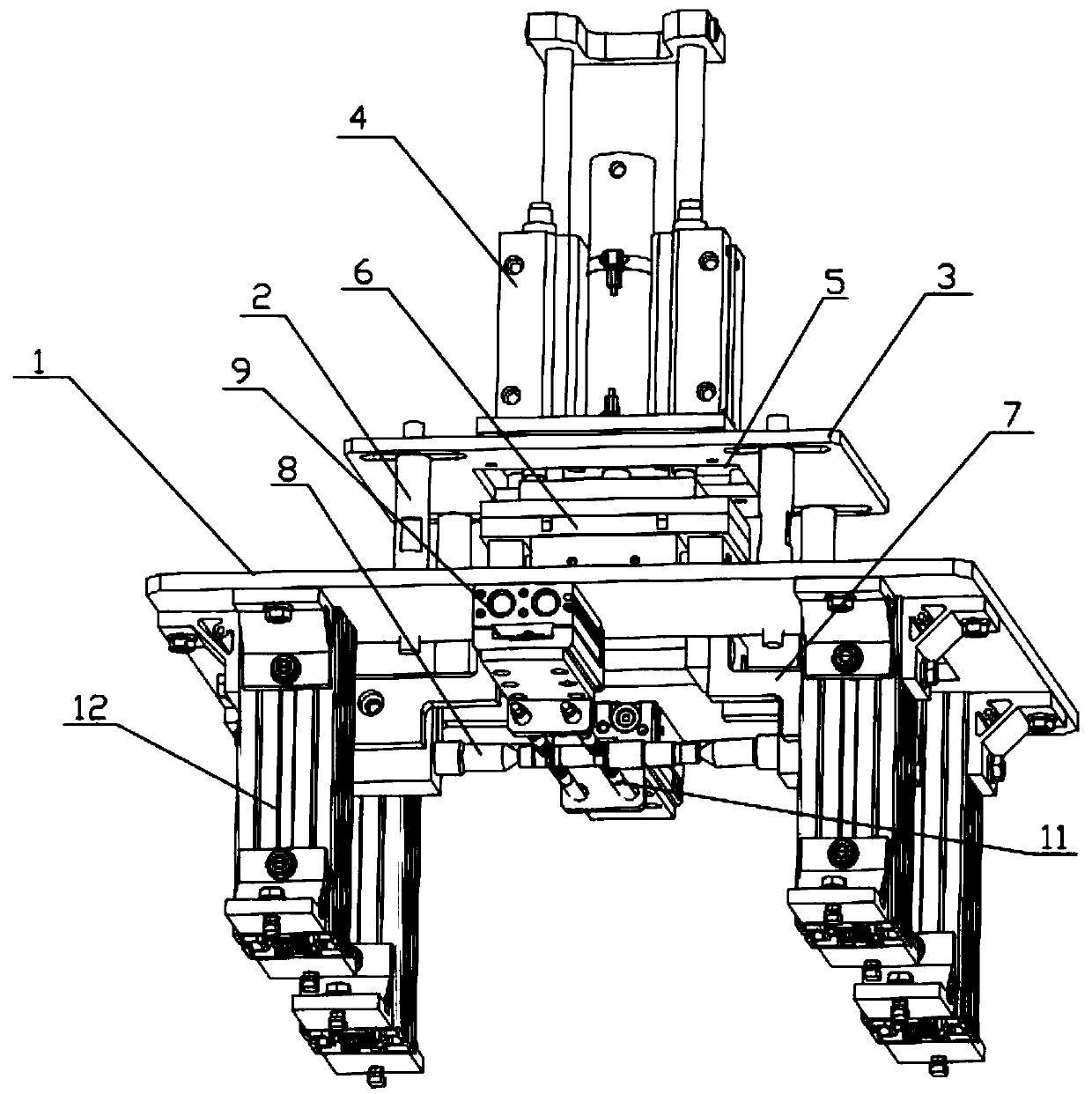
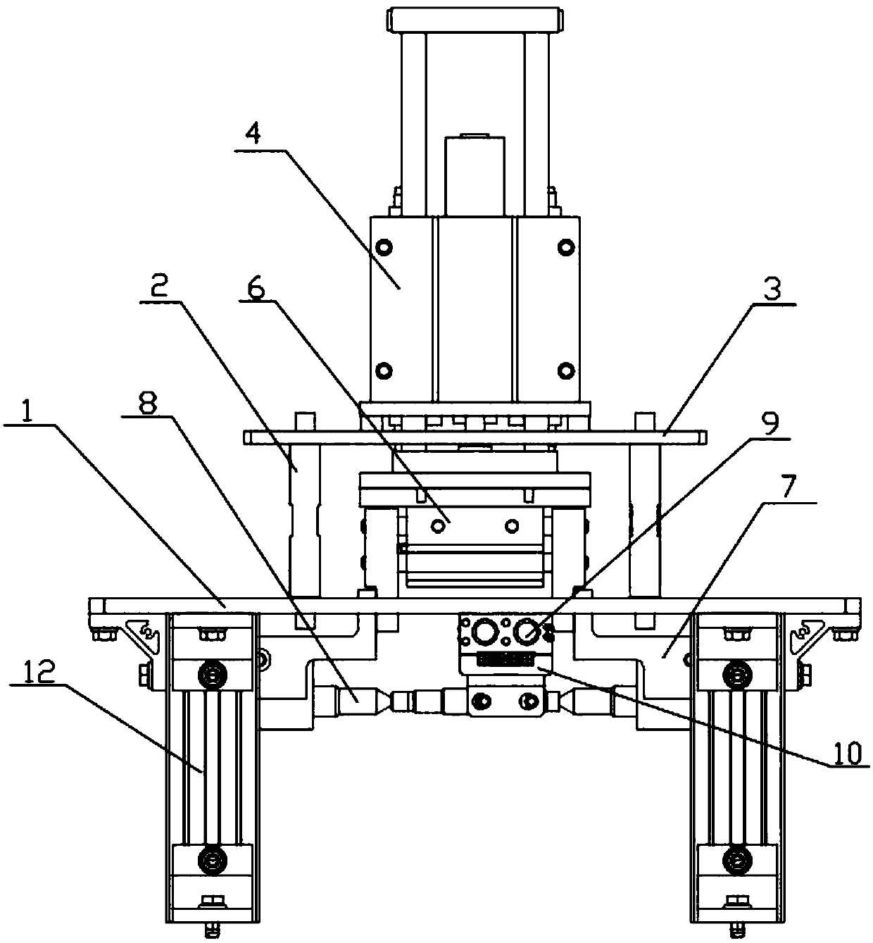
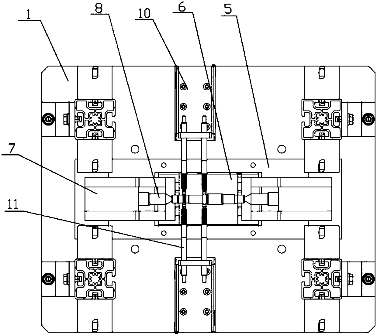
[0017] Such as figure 1 , figure 2 as well as image 3 In the diameter detection mechanism of shaft parts shown in the figure, the horizontal base plate 1 is a rectangular plate, and the base plate is provided with 4 vertical columns 2 whose lower ends are connected with it, and the upper end of the column is provided with a horizontal rectangular support plate 3, and a vertical lifting cylinder is provided on the support plate 4. The base plate has a through hole 5 for the lifting cylinder to pass through. The piston end of the lifting cylinder is connected to a horizontal clamping cylinder 6. The clamping cylinder is a two-way cylinder, and the two piston ends are respectively connected to the top frame 7. Each top frame is equipped with a top 8, the two tops are coaxial and the tips are oppositely arranged, and the lower end surface of the base plate is provided...


PUM


Abstract

The invention relates to a diameter detection mechanism for shaft-class parts. A substrate is provided with a plurality of vertical uprights of which the lower ends are connected with the substrate; the upper ends of the vertical uprights are provided with a horizontal supporting plate; the supporting plate is provided with vertical lifting air cylinders; the piston ends of the lifting air cylinders are connected with a horizontal clamping air cylinder; two piston ends of the clamping air cylinder are connected with pushing tip frames; each pushing tip frames are provided with a pushing tip; the lower end surface of the substrate is provided with two opposite detection air cylinders; the detection air cylinders are vertical to the pushing tips; the piston ends of the detection air cylinders face a position between the two pushing tips; the piston end of each detection air cylinder is connected with a sensor frame; each sensor frame is provided with a contact type sensor; and the lowerend surface of the substrate is provided with a plurality of supports adjacent to the edges of the substrate. Compared with the prior art, the diameter detection mechanism of the invention has the advantages of high detection precision, accurate data and the like.

Description

technical field [0001] The invention relates to a detection mechanism, in particular to a detection mechanism for shaft parts. Background technique [0002] Shaft parts are very common parts in the machinery industry, and they are also very important parts. The shape error accuracy directly affects the motion performance and service life of the machine. With the development of the machinery industry, the requirements for shafts are getting higher and higher. When detecting the diameter of parts, the traditional detection is to use pure artificial vision detection or the combination of artificial vision with mechanical measuring tools and optical instruments. Manual detection often has disadvantages such as low efficiency, poor reliability, low detection accuracy, and high cost; using Industrial camera detection, the detection accuracy is not high, the detection data is not stable enough, and it is greatly affected by external light; neither manual nor industrial camera detec...

Claims


Application Information

Patent Timeline
Patent Type & Authority Applications(China)
IPC IPC(8): G01B21/10B65G47/90
CPCG01B21/10B65G47/901
Inventor 胡善成
Owner DALIAN DEMAISHI PRECISION TECH CO LTD
Learn More