
Centrifugal fan with impeller structure

A centrifugal fan and impeller technology, which is applied in mechanical equipment, machines/engines, liquid fuel engines, etc., can solve problems such as low exhaust air volume and wind pressure, increased noise and power consumption, and decreased user experience, achieving increased The effect of increasing air intake volume and air intake speed, wind speed and wind pressure, and increasing exhaust air volume and wind pressure

Pending Publication Date: 2018-03-13
KINGCLEAN ELECTRIC
View PDF11 Cites 2 Cited by
  • Summary
  • Abstract
  • Description
  • Claims
  • Application Information

AI Technical Summary

Problems solved by technology

[0003] In the existing centrifugal fan, limited by the structural design of the air duct, its exhaust air volume and wind pressure are relatively small. When more air volume and wind pressure need to be exhausted, it can only be achieved by increasing the power of the motor. This leads to an increase in noise and power consumption. For some small appliances and portable appliances, the increase in noise leads to a decline in user experience, and the increase in power consumption greatly reduces battery life.

Method used


Image

  • Centrifugal fan with impeller structure
  • Centrifugal fan with impeller structure
  • Centrifugal fan with impeller structure

Examples


Embodiment Construction

[0037] The present invention will be further described in detail below in conjunction with the accompanying drawings, and the aforementioned and other objects, features, aspects and advantages of the present invention will become more apparent, so that those skilled in the art can implement them with reference to the description. In the drawings, the shapes and dimensions may be exaggerated for clarity, and the same reference numerals will be used throughout to designate the same or like parts. In the following description, terms such as center, thickness, height, length, front, back, rear, left, right, top, bottom, upper, lower, etc. are based on the orientation or positional relationship shown in the drawings. In particular, "height" corresponds to the dimension from top to bottom, "width" corresponds to the dimension from left to right, and "depth" corresponds to the dimension from front to back. These relative terms are for convenience of description and are generally not ...


PUM


Abstract

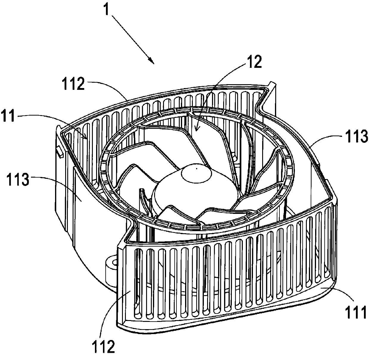
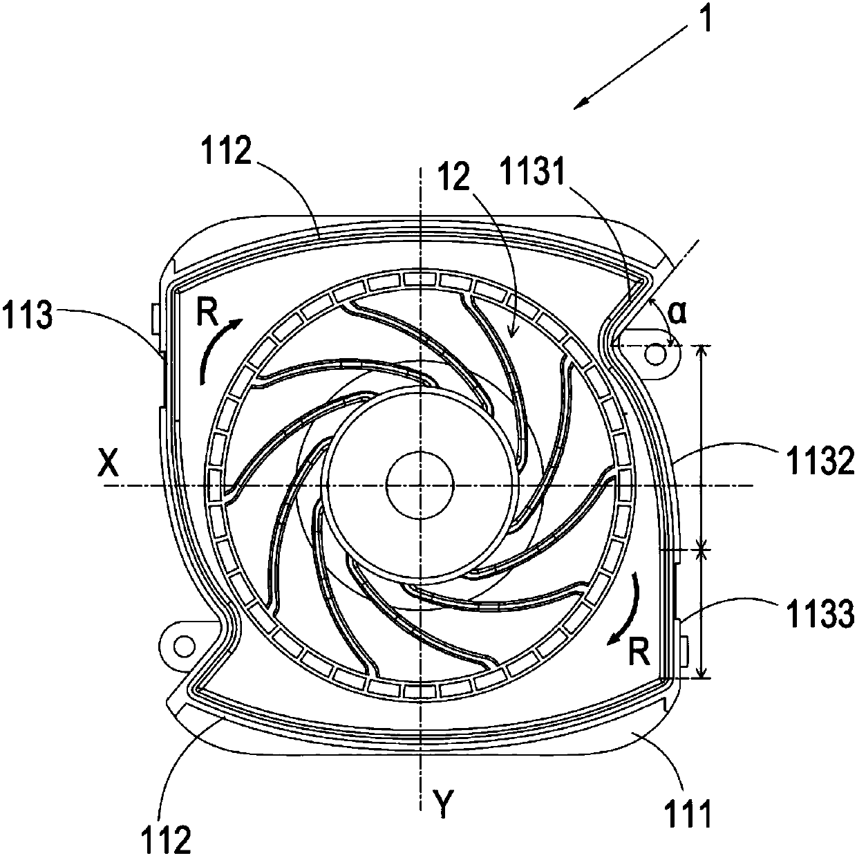
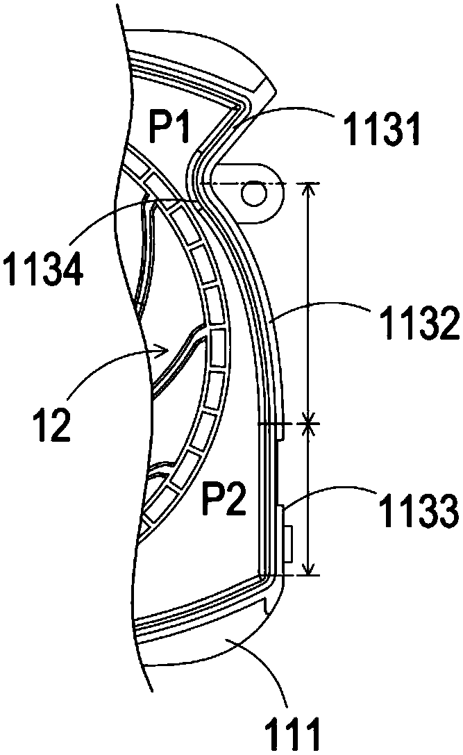
The invention discloses a centrifugal fan with an impeller structure. The centrifugal fan with the impeller structure comprises an impeller bin and an impeller assembly, wherein the impeller bin has certain inner space; and the impeller assembly is arranged in the impeller bin and is rotatably connected with the impeller bin, so that the impeller assembly can rotate relative to the impeller bin. The centrifugal fan with the impeller structure is characterized in that the impeller bin comprises a bottom wall, a plurality of air outlet side walls and a plurality of air pressing side walls; the air outlet side walls and the air pressing side walls are arranged at the edge of the bottom wall; the air outlet side walls and the air pressing side walls are arranged alternately and are successively connected end to end; a plurality of air outlets are formed in each air outlet side wall; and a V-shaped air pressing structure which is projected to the inner side of the impeller bin is arranged on each air pressing side wall. According to the centrifugal fan with the impeller structure, exhaust air rate and air pressure are high under the condition that the power of an input motor is not changed, air throwing is stable, turbulent flow is less, meanwhile, noises generated during running are further reduced, user experiences and endurance power are improved, and the market application prospect is good.

Description

technical field [0001] The invention relates to the field of centrifugal fans, in particular to a centrifugal fan with an impeller structure. Background technique [0002] The centrifugal fan is a mechanical structure that uses the input mechanical energy to increase the gas pressure and discharge the gas. It is widely used in ventilation, dust removal and cooling of factories, mines, tunnels, cooling towers, vehicles, ships and buildings; boilers and industrial Ventilation and induction of kilns; cooling and ventilation in air conditioning equipment and household appliances; drying and selection of grain; wind tunnel wind source and inflation and propulsion of hovercraft, etc. [0003] In the existing centrifugal fan, limited by the structural design of the air duct, its exhaust air volume and wind pressure are relatively small. When more air volume and wind pressure need to be exhausted, it can only be achieved by increasing the power of the motor. This leads to an increa...

Claims


Application Information

Patent Timeline
Patent Type & Authority Applications(China)
IPC IPC(8): F04D29/28
CPCF04D29/281
Inventor 倪祖根
Owner KINGCLEAN ELECTRIC
Learn More