Lens mounting base adjustable in multiple degrees of freedom

A lens mount, degree of freedom technology, applied in installation, optics, instruments, etc., can solve the problems of inaccurate measurement results of the optomechanical system, restricted scope of application, and failure of the optomechanical system, achieving fewer parts and a wide range of applications. , the effect of simple operation

Pending Publication Date: 2018-03-06
SOUTHWEST PETROLEUM UNIV
View PDF0 Cites 2 Cited by
  • Summary
  • Abstract
  • Description
  • Claims
  • Application Information

AI Technical Summary

Problems solved by technology

[0002] At present, the rapid development of optical-mechanical systems makes the design of various optical path systems simpler and easier to implement. However, for the installation of lenses, the general technical means is to design a special mount according to the needs of lens installation. Errors in the design or production process of the mounting seat can lead to inaccurate measurement results of the optomechanical system, and the serious consequence is the failure of the entire optomechanical system, and this mounting seat can only be applied to a specific optomechanical system. In the system, the scope of application is greatly restricted; in addition, although some lens mounts have a certain degree of freedom adjustment function, the degree of freedom that can be adjusted is limited to angle adjustment or inclination adjustment, which cannot fully meet the requirements. The requirements that may be encountered in actual use, so it is particularly important to design a lens mount that can be adjusted in angle and inclination

Method used


Image

  • Lens mounting base adjustable in multiple degrees of freedom
  • Lens mounting base adjustable in multiple degrees of freedom
  • Lens mounting base adjustable in multiple degrees of freedom

Examples


Embodiment Construction

[0023] The specific implementation manner of the invention will be described in detail below in conjunction with the accompanying drawings.

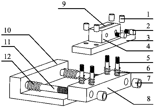
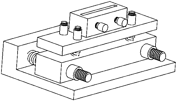
[0024] For the installation of the plane mirror, the specific implementation method is as follows: Please refer to figure 1 , This embodiment provides a multi-degree-of-freedom adjustable lens mounter, which includes a base 10 , an angle adjustment platform 8 , an inclination adjustment platform 3 , and a plane mirror lens fastening seat 4 .

[0025] Such as figure 1 As shown, for the base 10, it is a right-angle structure. When installing, the lower bottom surface of the base is connected with the optical experiment table. Two angle adjustment platform installation shafts 11 are arranged symmetrically on the side of the base. It is integrally formed with the installation shaft 11 of the angle adjustment platform, and the top end of the installation shaft 11 is provided with threads.

[0026] Such as figure 1 As shown, for the angle a...


PUM


Abstract

The invention provides a lens mounting base adjustable in multiple degrees of freedom and relates to the technical field of optical-mechanical system assembly design. The lens mounting base is formedby four parts of a base, an angle adjusting table, an inclination adjusting table and a lens fasting seat. Angle adjusting springs and the angle adjusting table are mounted on two installation shaftsprotruding out of the side edge of the base sequentially, and two adjusting screws are rotated respectively so as to realize the angle adjusting purpose; four inclination adjusting springs and the inclination adjusting table are mounted on four installation shafts protruding out of the upper surface of the angle adjusting table sequentially, and the four adjusting nuts are rotated respectively soas to realize the lens inclination adjusting purpose; according to the lens mounting base adjustable in multiple degrees of freedom, the structure is simple, the installation angle and the inclinationof the lens can be adjusted simultaneously, and a greater practical value is provided for the design of the optical-mechanical system.

Description

technical field [0001] The invention relates to the technical field of optical-mechanical system component design, in particular to a multi-degree-of-freedom adjustable lens mount. Background technique [0002] At present, the rapid development of optical-mechanical systems makes the design of various optical path systems simpler and easier to implement. However, for the installation of lenses, the general technical means is to design a special mount according to the needs of lens installation. Errors in the design or production process of the mounting seat can lead to inaccurate measurement results of the optomechanical system, and the serious consequence is the failure of the entire optomechanical system, and this mounting seat can only be applied to a specific optomechanical system. In the system, the scope of application is greatly restricted; in addition, although some lens mounts have a certain degree of freedom adjustment function, the degree of freedom that can be ad...

Claims


Application Information

Patent Timeline
IPC IPC(8): G02B7/02G02B7/182
CPCG02B7/023G02B7/182
Inventor 徐伟郭智勇刘丹匡珺洁吴攀
Owner SOUTHWEST PETROLEUM UNIV
Why Eureka
Try Eureka