


Quick Research
Generate reliable direction feasibility study reports for your R&D in just a few steps.

Technical Q&A
Discover and master advanced knowledge NOW. Basics, ideas, possibilities, all at once.

Find Solutions
As an expert in R&D theories, this can generate solutions to your technical problems instantly.

Evaluate Feasibility
Analyze your overall solution with one click, know your potential R&D risks in advance.

Monitor Landscape
Get weekly tech updates, stay abreast of the latest tech innovations and key insights.
Anti-electrostatic card tray structure
An anti-static, card tray technology, applied in the direction of static electricity, electrical components, transmission systems, etc., can solve the problem of static electricity caused by the friction between the card tray cap and the card tray, so as to avoid adverse effects and improve the user experience
- Summary
- Abstract
- Description
- Claims
- Application Information
AI Technical Summary
Problems solved by technology
Method used
Image

Examples
Embodiment 1
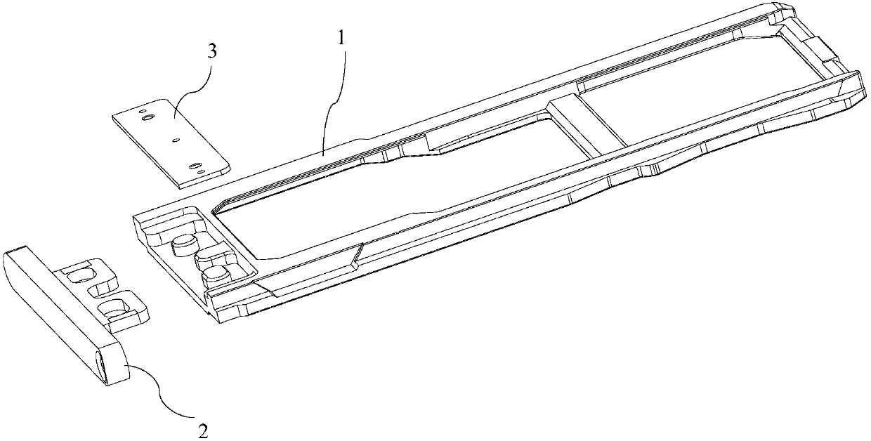
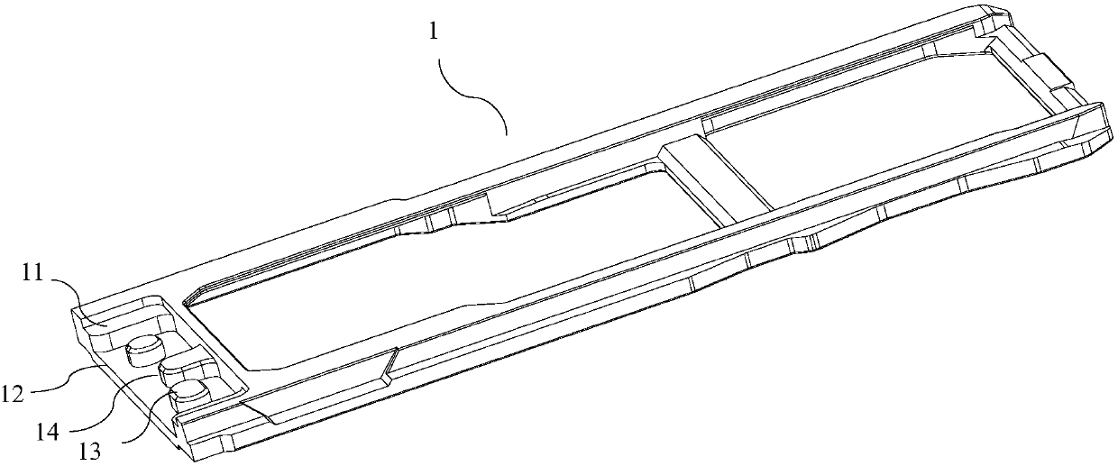
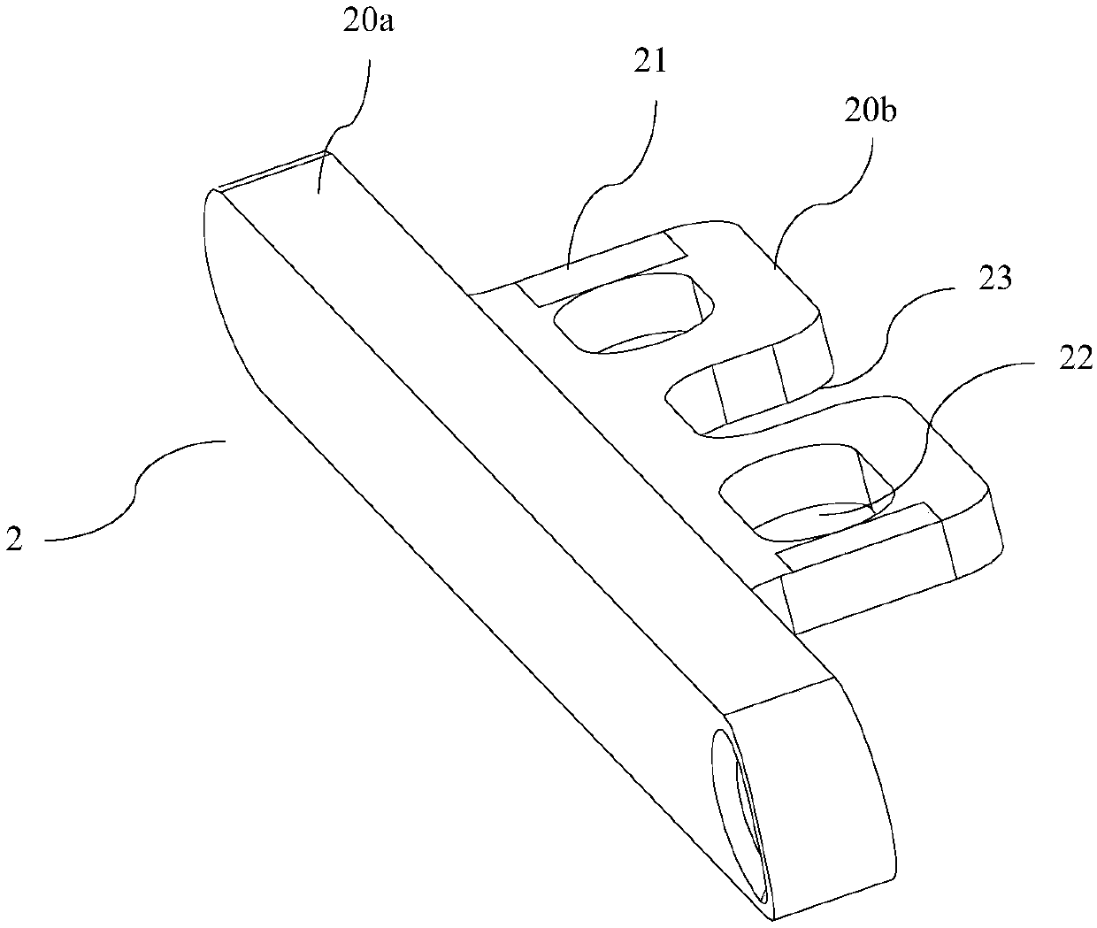
[0025] Such as Figure 2-3 As shown, the side wall of the end where the card tray 1 is connected with the card holder cap 2 is provided with a first groove 11, and the bottom wall of the first groove 11 is provided with a second groove 12, and the first groove 11 There is a step between the bottom wall of the second groove 12 and the bottom wall of the second groove 12 . Wherein, at least one connecting column 13 is formed on the bottom wall of the second groove 12, and a through hole 22 corresponding to the connecting column 13 is opened on the card tray cap 2, and the card tray cap 2 is sleeved on the connecting column through the through hole 22. Column 13. In this embodiment, the number of connecting columns 13 is two, and in other embodiments, the number of connecting columns 13 may also be one or more.
[0026] At least one locking portion 14 is formed on the bottom wall of the second groove 12 , and an engaging hole 23 is opened on the cap 2 , and the engaging hole 23...
Embodiment 2
[0035]The difference with embodiment 1 is: the Cato cap 2 is still a Cato cap made of conductive metal, and an oxide film layer is formed on the surface of the Cato cap 2, and the Cato cap 2 is connected with the first conductive part 31. The corresponding position is protruded with a protrusion as the second conductive part 21, and the protrusion is exposed to the outside through the oxide film layer. The groove is coated with a conductive metal layer or the soldering part 3 is made of conductive metal. Wherein, the conductive metal and the conductive metal layer can be made of aluminum, aluminum alloy, copper, gold or silver.
[0036] The antistatic card support structure of this embodiment is an alternative structure of Embodiment 1, which can also realize the export of static electricity generated by aggregation, realize the antistatic effect, avoid adverse effects on the performance of mobile phones, and improve user experience Spend.
[0037] The serial numbers of the ...
PUM
 Abstract
Description
Claims
Application Information
 - R&D Engineer
- R&D Manager
- IP Professional
- Industry Leading Data Capabilities
- Powerful AI technology
- Patent DNA Extraction
Browse by: Latest US Patents, China's latest patents, Technical Efficacy Thesaurus, Application Domain, Technology Topic, Popular Technical Reports.
© 2024 PatSnap. All rights reserved.Legal|Privacy policy|Modern Slavery Act Transparency Statement|Sitemap|About US| Contact US: help@patsnap.com