
Skimming and mud scraping device

A technology of scraper and mounting plate, which is applied in the direction of settling tanks, chemical instruments and methods, separation methods, etc., can solve the problems of poor connection reliability, high false trigger probability, and the scraper cannot be turned over, so as to achieve high reliability and reduce agitation Degree, the effect that is not easy to trigger by mistake

Active Publication Date: 2018-02-09
扬州青青环保成套设备有限公司
View PDF1 Cites 6 Cited by
  • Summary
  • Abstract
  • Description
  • Claims
  • Application Information

AI Technical Summary

Problems solved by technology

[0003] However, after actual use, the applicant found that this case still has the following defects due to its complicated mechanism: 1. Since the case requires high precision for each part, it is very easy to get stuck between the parts As a result, the scraper cannot be turned over or reset, and has a high probability of false triggering; 2. In this case, the connection reliability between the "scraper" and the "running belt" is poor, so it is under force. Finally, especially when scraping out the bottom mud, it is very easy to cause problems such as failure of mud scraping due to accidental overturning; 3. In this case, after the scraper is overturned, it will still maintain a certain angle with the running belt, so that it will still be relatively large. Agitation of pool water

Method used


Image

  • Skimming and mud scraping device
  • Skimming and mud scraping device
  • Skimming and mud scraping device

Examples


Embodiment 1

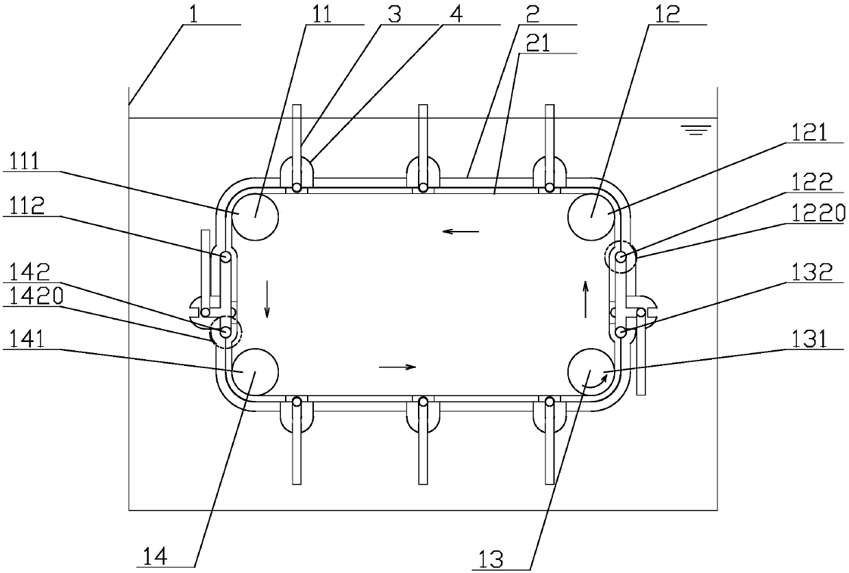
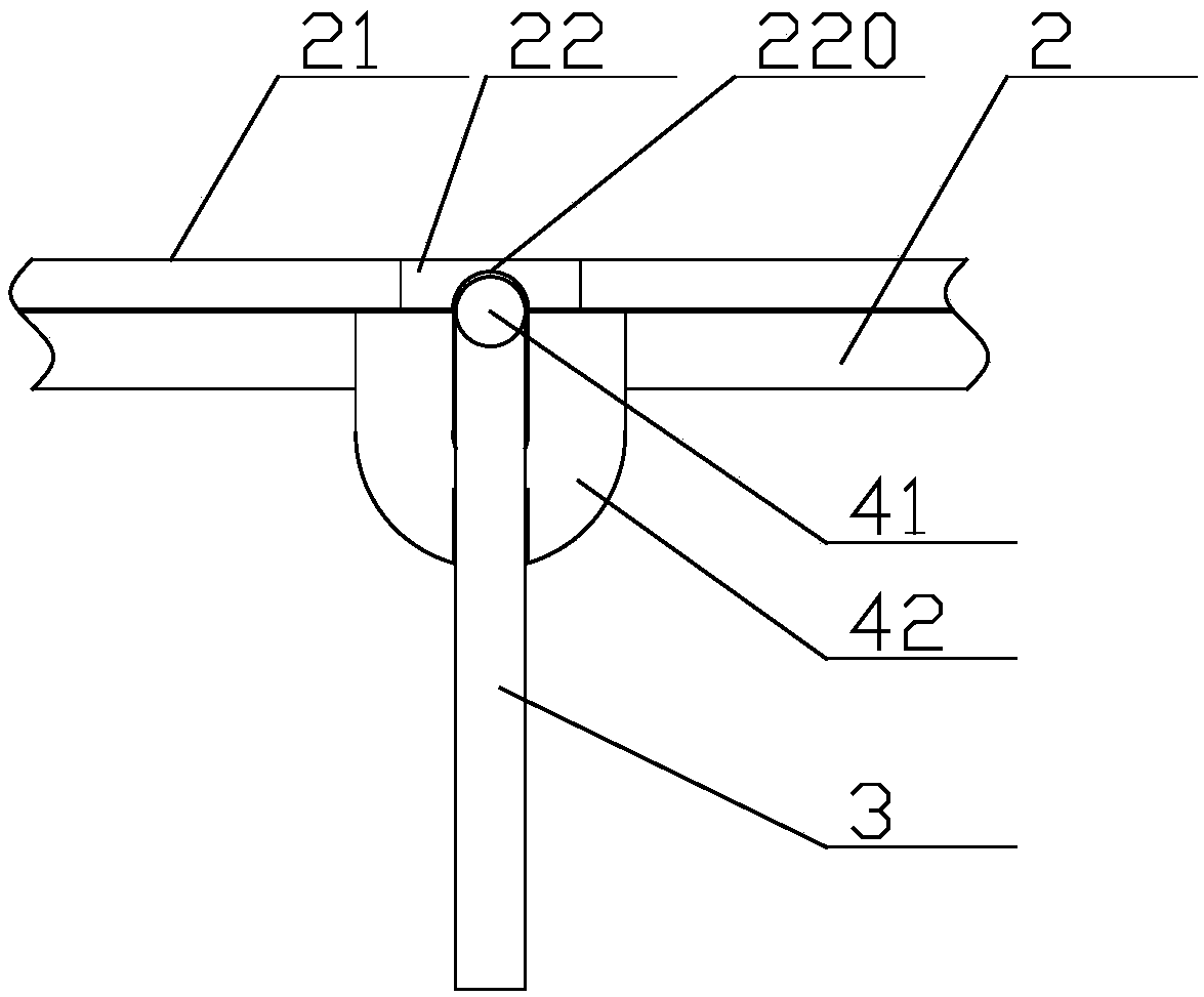
[0056] Example as Figure 1-9 As shown, the inner side of the conveyor belt 2 is further provided with an auxiliary conveyor belt 21, and a plurality of magnets 22 are fixedly connected to the auxiliary conveyor belt 21, and the magnets 22 correspond to the connecting assembly 4 one by one;

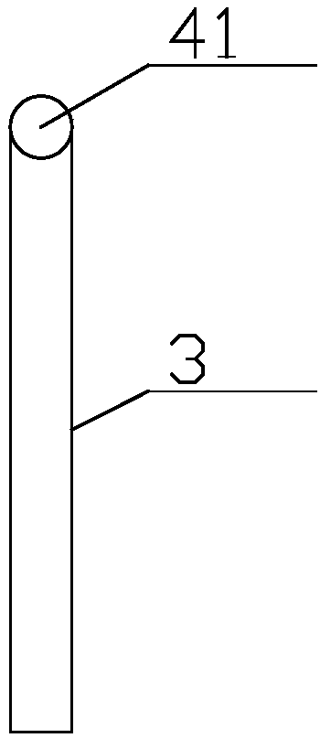
[0057] The connecting assembly 4 includes a main shaft 41, a mounting seat 42 and a pair of connecting plates 43, the conveyor belt 2 has a fracture, the mounting seat 42 is arranged perpendicular to the conveyor belt 2, and its two ends are respectively fixedly connected to both ends of the fracture The end surface of the mounting seat 42 facing the magnet 22 is provided with a U-shaped slot 421 for accommodating the spindle 41, the end surface of the mounting seat 42 facing away from the magnet 22 is semicircular, and the middle of the end surface is provided with The accommodating groove 422 for accommodating the scraper 3, the main shaft 41 is made of magnetic material, the main shaft 41 ...

Embodiment 2

[0067] Example two Figure 10-20 As shown, the connecting assembly 4 includes a rotating shaft 44, an inner drive tooth 45, an outer drive plate 46, and a pair of mounting plates 47. The conveyor belt has a cutout. The mounting plates 44 are arranged perpendicular to the conveyor belt 2 and have two ends. They are respectively fixedly connected to the two ends of the fracture, the rotating shaft 44 is fixedly connected to one end of the scraper 3, and both ends of the rotating shaft 44 are hinged to the two mounting plates 44, and the internal driving teeth 45 are fixedly connected to the rotating shaft 44, And extend to the outside of the mounting plate 3, the external drive teeth 46 are hinged to one of the mounting plates 44 on the side away from the scraper 3 through the central shaft 460, and the central shaft 460 is in contact with the rotating shaft 44; in this way, the internal drive teeth The rotation of will drive the scraper to flip toward one side, and the rotation ...


PUM


Abstract

The invention discloses a skimming and mud scraping device, relates to the field of sewage treatment equipment, and particularly relates to improvement on skimming and mud scraping machines. The skimming and mud scraping device is exquisite in structure, good in stability and high in reliability and is good in structural strength during mud scraping and skimming, and false triggering can be prevented. The skimming and mud scraping device is arranged in a settling pond and comprises a first belt pulley, a second belt pulley, a third belt pulley, a fourth belt pulley, a conveyor belt, a plurality of scraping plates and a plurality of connecting assemblies. The first belt pulley and the second belt pulley are arranged at two ends of a location which is positioned below the internal liquid level of the settling pond, the third belt pulley and the fourth belt pulley are arranged at two ends of the upper portion of the bottom surface of the settling pond, and the conveyor belt is annularly sequentially wound on the first belt pulley, the second belt pulley, the third belt pulley and the fourth belt pulley. The skimming and mud scraping device integrally has the advantages that the skimming and mud scraping device is exquisite in structure, good in stability and high in reliability and is good in structural strength during mud scraping and skimming, the false triggering can be prevented, and the stirring degree of pond water can be lowered to a great extent.

Description

Technical field [0001] The invention relates to the field of sewage treatment equipment, in particular to the improvement of a slag skimming and mud scraper. Background technique [0002] The sewage treatment sedimentation tank usually settles the sludge at the bottom of the tank when it is working, and accumulates bubbles and foam on the water surface of the tank. In response to this, the applicant applied for a Chinese invention patent named "a slag skimmer and mud scraper" with the application number "201210065220.3" on March 13, 2012, and proposed a patent in the case The scraper can be automatically turned over to avoid the technical solution of stirring the liquid in the pool. [0003] However, after actual use, the applicant found that the case still brought the following defects due to the complexity of the mechanism: 1. Because the case requires high precision of each component, it is very easy to get sundries between the components. As a result, the scraper cannot be tu...

Claims


Application Information

Patent Timeline
Patent Type & Authority Applications(China)
IPC IPC(8): B01D21/06B01D21/20
CPCB01D21/06B01D21/20
Inventor 孙正甫
Owner 扬州青青环保成套设备有限公司
Learn More