Array substrate, display panel and driving method of array substrate

A technology for array substrates and display areas, applied to static indicators, data processing input/output processes, instruments, etc., can solve the problem of increasing the non-display area of ​​the display panel, and achieve the effect of reducing the area

Active Publication Date: 2020-11-13
XIAMEN TIANMA MICRO ELECTRONICS
View PDF9 Cites 0 Cited by
  • Summary
  • Abstract
  • Description
  • Claims
  • Application Information

AI Technical Summary

Problems solved by technology

Undoubtedly, widening the distance between the edge of the shift register adjacent to the display area and the boundary line between the display area and the non-display area will increase the area of ​​the non-display area of ​​the display panel, which is contrary to the development trend of narrow borders

Method used


Image

  • Array substrate, display panel and driving method of array substrate
  • Array substrate, display panel and driving method of array substrate
  • Array substrate, display panel and driving method of array substrate

Examples


Embodiment Construction

[0037] The present invention will be further described in detail below in conjunction with the accompanying drawings and embodiments. It should be understood that the specific embodiments described here are only used to explain the present invention, but not to limit the present invention. In addition, it should be noted that, for the convenience of description, only some structures related to the present invention are shown in the drawings but not all structures.

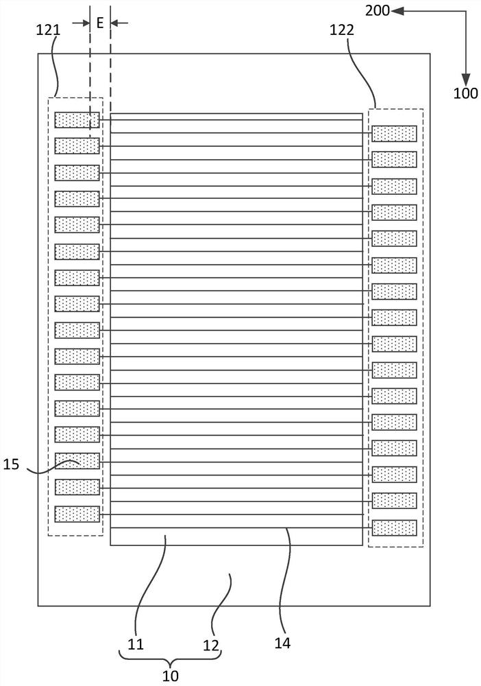
[0038] figure 1 It is a structural schematic diagram of an existing array substrate. No pressure sensor is provided on this array substrate. see figure 1 , the array substrate includes a base substrate 10 . The base substrate 10 includes a display area 11 and a non-display area 12 surrounding the display area 11, the base substrate 10 also includes a first direction 100 and a second direction 200 parallel to the base substrate 10, the first direction 100 and the second direction 200 Two directions 200 cross. ...


PUM


Abstract

Provided are an array substrate, a display panel and a driving device. In the array substrate, a pressure sensor is disposed between adjacent two of the shift registers at either of the two sides of the display region; the scanning lines include a first set of scanning lines and a second set of scanning lines; the extending lines of the first set of scanning lines pass the pressure sensors in the first region, and the first set of scanning lines are electrically connected to the corresponding shift registers in the second region.

Description

technical field [0001] Embodiments of the present invention relate to a touch pressure detection technology, and in particular to an array substrate, a display panel, and a driving method for the array substrate. Background technique [0002] At present, display panels are widely used in electronic devices such as mobile phones, tablet computers, and information inquiry machines in halls of public places. In this way, the user can operate the electronic device only by touching the mark on the electronic device with a finger, which eliminates the user's dependence on other input devices (such as keyboard and mouse) and makes human-computer interaction easier. [0003] In order to better meet user needs, a pressure sensor for detecting the amount of touch pressure when the user touches the display panel is usually provided in the display panel, so as to enrich the application range of the touch technology. But currently, a display panel includes a display area and a non-displ...

Claims


Application Information

Patent Timeline
Patent Type & Authority Patents(China)
IPC IPC(8): G09G3/20H01L27/12
CPCG09G3/20H01L27/1214G06F3/0412G06F2203/04105G09G2310/0267G09G2310/0281G09G2354/00G09G3/2092G09G2310/0205G09G2310/0286G09G2310/08
Inventor 涂骏杨康鹏王伟鹏许育民郑超
Owner XIAMEN TIANMA MICRO ELECTRONICS
Why Eureka
Try Eureka