


Quick Research
Generate reliable direction feasibility study reports for your R&D in just a few steps.

Technical Q&A
Discover and master advanced knowledge NOW. Basics, ideas, possibilities, all at once.

Find Solutions
As an expert in R&D theories, this can generate solutions to your technical problems instantly.

Evaluate Feasibility
Analyze your overall solution with one click, know your potential R&D risks in advance.

Monitor Landscape
Get weekly tech updates, stay abreast of the latest tech innovations and key insights.
Projection device, light source system and method for digitally controlling current
A light source system and digital current control technology, applied in light sources, electric light sources, lighting devices, etc., can solve problems such as inaccurate current control of projectors, strong transmission interference, and color distortion
- Summary
- Abstract
- Description
- Claims
- Application Information
AI Technical Summary
Problems solved by technology
Method used
Image

Examples
Embodiment 1
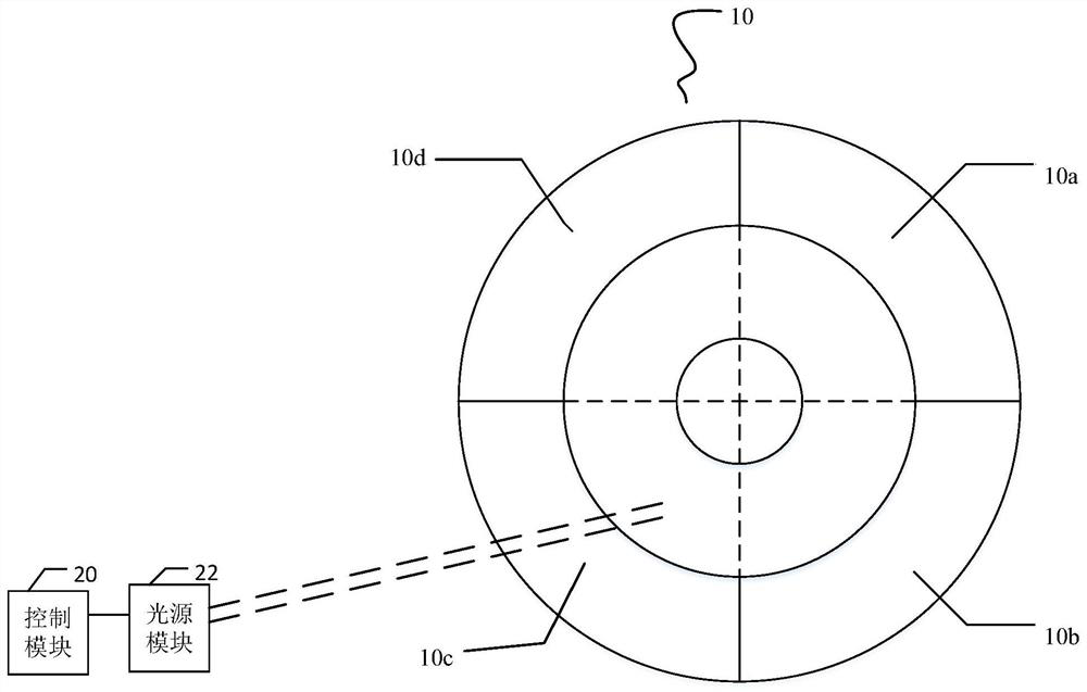
[0038] Such as figure 1 As shown, it is a schematic structural diagram of the control end of the light source system provided by Embodiment 1 of the present invention, which includes the wavelength conversion device 10 , the light source module 22 and the control module 20 .
[0039] Wherein, the light source module 22 is used for emitting source light. The light source module 22 may include multiple light sources, and the light sources may be laser diodes or other optical devices with controllable brightness.
[0040] Preferably, the plurality of light sources can also be divided into several groups according to actual needs, so as to realize independent control.
[0041] The wavelength conversion device 10 is partly on the light path of the light source module 22, which includes at least one subsection, and the wavelength conversion device 10 moves periodically so that the at least one subsection is located on the optical path of the source light.
[0042] It can be unders...
Embodiment 2
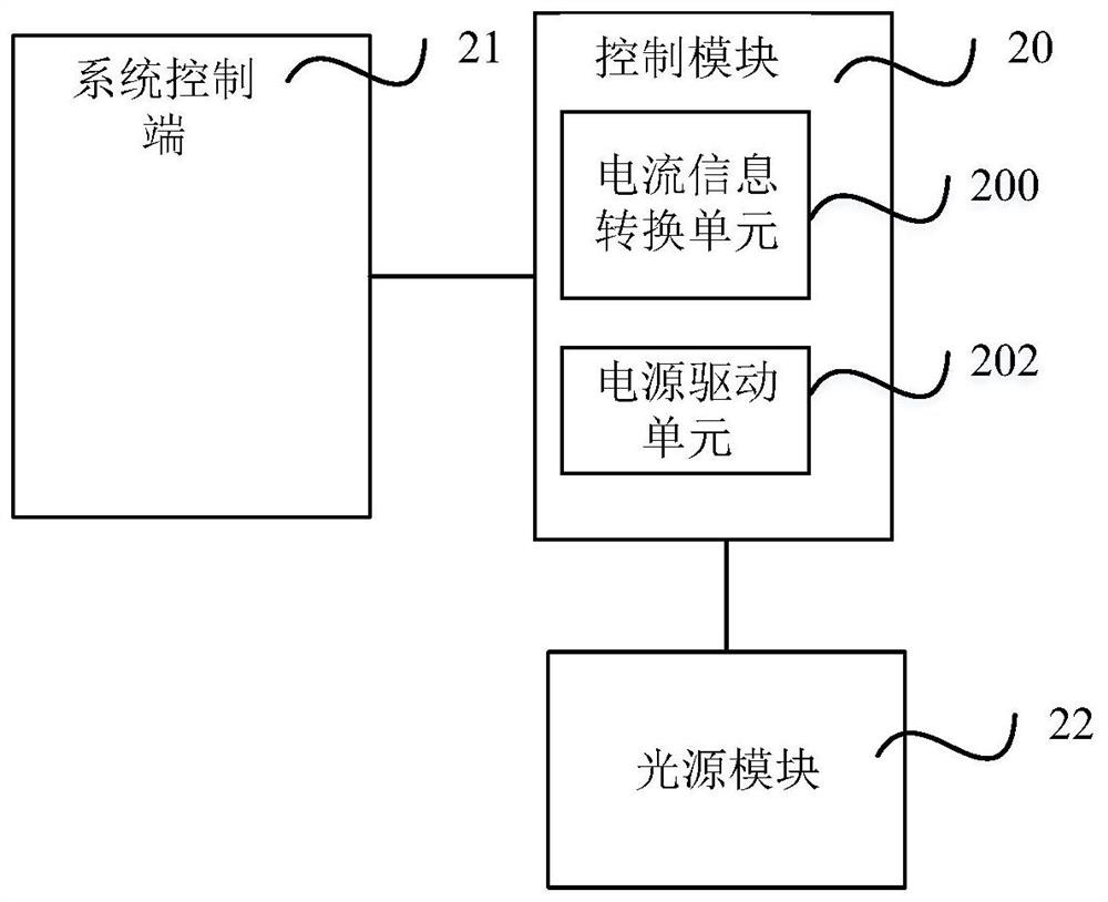
[0059] figure 2 It is a schematic diagram of the connection between the control module and other components provided by Embodiment 2 of the present invention. exist figure 2 Among them, the control module 20 is connected to the system control terminal 21 and the light source module 22 respectively.
[0060] The light source module 22 is electrically connected with the control module 20, and is used for generating corresponding source light according to the constant current output by the control module 20, and projecting the source light onto the wavelength conversion device to generate stimulated light.
[0061] The control module 20 receives the digital current control information sent by the system control terminal 21, and converts the digital current control information into a voltage or current signal to control the input terminal of the power drive unit to finally control the constant output current.
[0062] The control module 20 includes a current information conver...
Embodiment 3
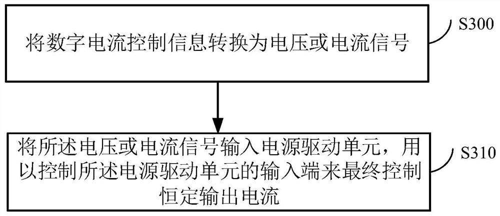
[0073] image 3 It is a flow chart of the method for controlling current at the control end of the light source system provided by Embodiment 3 of the present invention. The method includes the steps of:
[0074] Step S300, receiving digital current control information, and converting the digital current control information into a voltage or current signal;
[0075] Step S310, input the voltage or current signal into the power drive unit to control the input terminal of the power drive unit to finally control the constant output current.
[0076] Further, step S300 is to convert the digital current control information into a voltage or current signal in the following manner:
[0077] converting said digital current control information directly into a voltage or current signal; or
[0078] The digital current control information is converted into current digital information, and the current digital information is converted into a corresponding resistance value, and then conv...
PUM
 Abstract
Description
Claims
Application Information
 - R&D Engineer
- R&D Manager
- IP Professional
- Industry Leading Data Capabilities
- Powerful AI technology
- Patent DNA Extraction
Browse by: Latest US Patents, China's latest patents, Technical Efficacy Thesaurus, Application Domain, Technology Topic, Popular Technical Reports.
© 2024 PatSnap. All rights reserved.Legal|Privacy policy|Modern Slavery Act Transparency Statement|Sitemap|About US| Contact US: help@patsnap.com