
Retraction method of fan-shaped area in fully-mechanized mining retraction face

A fan-shaped area and working face technology, applied in mining equipment, earth square drilling, mine roof supports, etc., can solve problems such as difficult roof management, roof collapse, and poor safety

Active Publication Date: 2020-03-20
CHNA ENERGY INVESTMENT CORP LTD +1
View PDF5 Cites 0 Cited by
  • Summary
  • Abstract
  • Description
  • Claims
  • Application Information

AI Technical Summary

Problems solved by technology

Due to the shortcomings of the support method of the one-beam and three-column steel shed, such as large roof control area, high pressure on the roof in the fan-shaped area, difficulty in roof management, and high safety risks, accidents such as large-scale roof sinking, roof leakage, and knockdown of the shed are prone to occur, especially On the working face with soft roof or bottom and severe mudification, the bottom of the single hydraulic prop is seriously drilled, and the support strength is poor. When the one-beam and three-column steel shed is manually disassembled, the roof is prone to collapse and the safety is poor.
[0003] In addition, wooden piles are used to maintain the fan-shaped roof of the working face where the roof is broken, separated, and the mesh is seriously torn. Every other hydraulic support to be withdrawn is extracted from a hydraulic support to be withdrawn. After the hydraulic support is extracted, it is supported by a well-shaped wooden pile, and then Recirculation and retraction of hydraulic supports, no recycling of supporting wood stacks, high retraction costs

Method used


Image

  • Retraction method of fan-shaped area in fully-mechanized mining retraction face
  • Retraction method of fan-shaped area in fully-mechanized mining retraction face
  • Retraction method of fan-shaped area in fully-mechanized mining retraction face

Examples


Embodiment 1

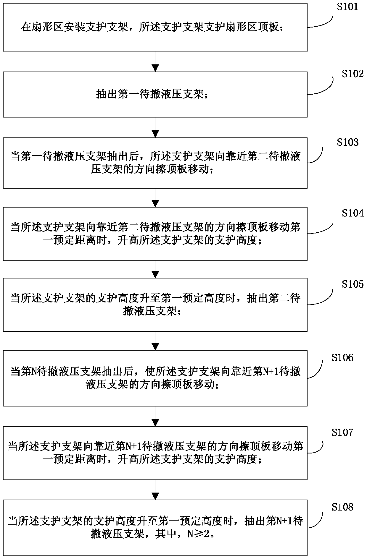
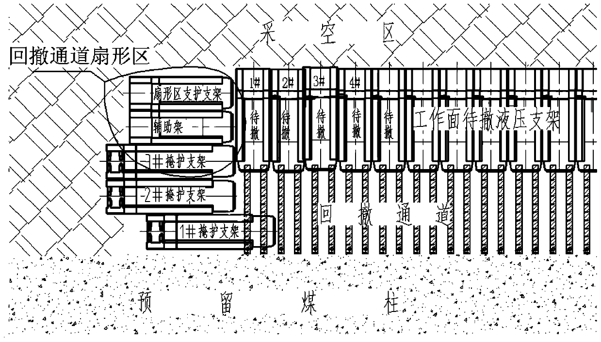
[0025] figure 1 It shows the flow chart of the method for retracting the fan-shaped area of ​​the fully-mechanized mining retraction working face according to the embodiment of the present invention, figure 2 It shows the support layout of the fan-shaped area of ​​the fully-mechanized mining retraction working face according to the embodiment of the present invention, which includes:

[0026] S101, installing a supporting bracket in the fan-shaped area, and the supporting bracket supports the top plate of the fan-shaped area;

[0027] The number of supporting brackets can be set according to the supporting area of ​​the sector roof. The supporting bracket supports the roof of the fan-shaped area, and the supporting force of the supporting bracket on the roof before moving is the initial supporting force of the supporting bracket.

[0028] S102, pulling out the first hydraulic support to be withdrawn;

[0029] All the hydraulic supports to be withdrawn are arranged in paral...

Embodiment 2

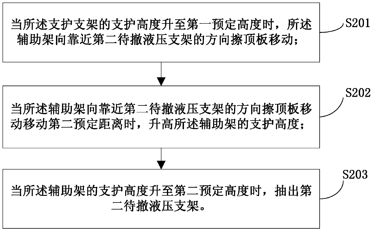
[0042] On the basis of Embodiment 1, the embodiment of the present invention is improved, optionally, as image 3 As shown, the S105 includes:

[0043]S201, when the support height of the support bracket rises to a first predetermined height, the auxiliary frame moves toward the top plate in a direction close to the second hydraulic support to be withdrawn;

[0044] Among them, the auxiliary frame is set adjacent to the support bracket, such as figure 2 As shown, the auxiliary frames are arranged side by side on the side of the support bracket close to the withdrawal channel. The auxiliary frame supports the roof of the fan-shaped area with the auxiliary support bracket. The supporting force on the roof before the auxiliary frame moves is the initial supporting force of the auxiliary frame.

[0045] S202. When the auxiliary frame moves toward the roof in a direction close to the second hydraulic support to be withdrawn and moves a second predetermined distance, raise the s...

Embodiment 3

[0059] On the basis of the second embodiment, the embodiment of the present invention is improved, optionally, as Figure 5 As shown, S203 includes:

[0060] S301, when the support height of the auxiliary frame rises to a second predetermined height, the cover support moves toward the top plate in a direction close to the second hydraulic support to be withdrawn;

[0061] Wherein, the shield bracket is arranged adjacent to the auxiliary frame, and the auxiliary frame is located between the shield bracket and the support bracket, such as figure 2 shown. Shield brackets are also used to support the roof of the sector. The cover support can adopt hydraulic support. The supporting force of the shielding bracket on the top plate before moving is the initial supporting force of the shielding bracket.

[0062] S302. When the shield bracket moves a third predetermined distance to the top plate in a direction close to the second hydraulic support to be withdrawn, raise the support...


PUM


Abstract

The embodiment of the invention discloses a retracement method for a fan section of a fully-mechanized coal mining retracement working face. The retracement method comprises the steps that a supporting support is mounted in the fan section, wherein the supporting support supports a fan section top plate; a first hydraulic support to be retraced is drawn out; after the first hydraulic support to beretracted is drawn out, the supporting support moves in the direction close to a second hydraulic support to be retraced by rubbing the top plate; when the supporting support moves in the direction close to the second hydraulic support to be retraced by rubbing the top plate for a first preset distance, the supporting height of the supporting support is increased; when the supporting height of the supporting support is increased to first preset height, the second hydraulic support to be retraced is drawn out. According to the retracement method, the retracement efficiency can be improved, andthe retracement cost can be reduced.

Description

technical field [0001] The embodiment of the present invention relates to the technical field of coal mining, and in particular to a method for withdrawing a fan-shaped area of ​​a fully-mechanized mining withdrawing working face. Background technique [0002] When retracting the hydraulic support in the fully mechanized mining face, the existing method is to use a cover support to maintain the roof of the retracted channel of the fully mechanized mining face, and for the sector area of ​​the retracted channel of the fully mechanized mining face, use a single hydraulic prop Cooperate with the π-shaped beam shed, that is, "one beam and three pillars steel shed" to maintain the roof. When the first hydraulic support to be withdrawn close to the fan-shaped area is retracted, two steel sheds with one beam and three columns need to be erected on the roof of the original position of the first hydraulic support, and then the two steel sheds with one beam and three columns in the fa...

Claims


Application Information

Patent Timeline
Patent Type & Authority Patents(China)
IPC IPC(8): E21D23/16E21D23/26
CPCE21D23/16E21D23/26
Inventor 张永强王林马忠昌张智福王占亭康泽义郭自文蒋贡友黄文勋马军祁刚
Owner CHNA ENERGY INVESTMENT CORP LTD
Learn More