A municipal road compaction device that can be automatically controlled

A tamping device and technology for municipal roads, applied in soil protection, construction, infrastructure engineering, etc., can solve the problems of increased transportation costs, high labor intensity, poor tamping effect, etc., to improve accuracy and stability, and reduce labor The effect of strength and easy operation

Active Publication Date: 2018-12-21
张家港和智珅知识产权有限公司
View PDF5 Cites 0 Cited by
  • Summary
  • Abstract
  • Description
  • Claims
  • Application Information

AI Technical Summary

Problems solved by technology

[0002] With the continuous development of the social economy and the continuous improvement of the construction level, it is often necessary to tamp the road subgrade and the road surface during road construction; at present, the tamping of the ground level and the subgrade is often done manually, but there is a need for manual tamping. The shortcomings of poor effect and low compacting efficiency; although some mechanized compacting machines have appeared on the market at present, such compacting machines need to manually grasp the forward direction of the compacting machine, so there is labor intensity and the direction of the compacting machine. The disadvantage of being difficult to control. In addition, if you move the compactor, you need to use external auxiliary machinery, which increases the cost of transportation and cannot be widely used in the field of compaction machinery.

Method used


Image

  • A municipal road compaction device that can be automatically controlled
  • A municipal road compaction device that can be automatically controlled
  • A municipal road compaction device that can be automatically controlled

Examples


Embodiment Construction

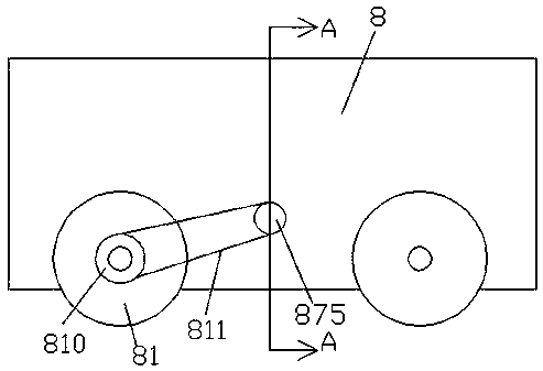
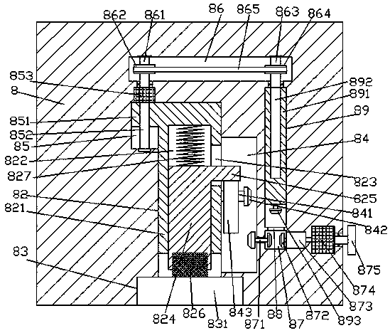
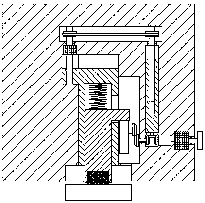
[0019] Such as Figure 1-Figure 4 As shown, an automatically controlled municipal road compacting device of the present invention includes a compacted car body 8 and two sets of walking rollers 81 that are rotatably arranged at the bottoms of the front and rear sides of the compacted car body 8, and the bottom of the compacted car body 8 A sinking groove 83 is arranged in the end surface, and the inner top wall of the sinking groove 83 is connected with a lifting sliding groove 82 extending upward, and the inner wall of the compacted car body 8 above the lifting sliding groove 82 is provided with left and right extending settings. The first transmission cavity 86 of the lifting sliding groove 82 is connected with the second transmission cavity 84 in the inner wall on the right side, and the first guide groove 85 is connected in the top of the left inner wall of the lifting sliding groove 82. The top of the first guide groove 85 is opposite to the bottom of the left extension e...


PUM


Abstract

The invention discloses a municipal road compaction device capable of being automatically controlled. The municipal road compaction device comprises a compaction vehicle body and two sets of travelingrollers rotatably arranged at the bottoms of the front side and the rear side of the compaction body. A sinking groove is formed in the bottom end face of the compaction vehicle body; a lifting sliding groove extending upwards is formed in the inner top wall of the sinking groove in a communicating mode; a first transmission cavity extending in the left-right direction is formed in the position,above the lifting sliding groove, of the inner wall body of the compaction vehicle body; a second transmission cavity is formed in the inner wall of the right side of the lifting sliding groove in a communicating mode; a first guiding groove is formed in the top of the inner wall of the left side of the lifting sliding groove in a communicating mode; the top of the first guiding groove and the bottom of the extending tail end of the left side of the first transmission cavity are in an opposite state; a first thread rod extending up and down is arranged in the first guiding groove; the extending tail end of the top of the first thread rod is in matched connection with a first motor; and the outer surface of the first motor is embedded in the inner top wall of the first guiding groove and fixedly connected with the inner top wall of the first guiding groove. The structure is simple, operation is convenient, compaction precision and stability are improved, the labor intensity of workers is relieved, and the transport cost is reduced.

Description

technical field [0001] The invention relates to the technical field of road construction, in particular to an automatically controlled municipal road compacting device. Background technique [0002] With the continuous development of the social economy and the continuous improvement of the construction level, it is often necessary to tamp the road subgrade and the road surface during road construction; at present, the tamping of the ground level and the subgrade is often done manually, but there is a need for manual tamping. The shortcomings of poor effect and low compacting efficiency; although some mechanized compacting machines have appeared on the market at present, such compacting machines need to manually grasp the forward direction of the compacting machine, so there is labor intensity and the direction of the compacting machine. The disadvantage of being difficult to control. In addition, if the tamping machine is moved, it needs to use external auxiliary machinery, ...

Claims


Application Information

Patent Timeline
Patent Type & Authority Patents(China)
IPC IPC(8): E02D3/046
CPCE02D3/046
Inventor 黄铁
Owner 张家港和智珅知识产权有限公司
Why Eureka
Try Eureka