Control rod component and guide component structure applicable to supercritical reactor
A technology for guiding components and control rods, which is applied in the control of nuclear reactions, reactors, and reduction of greenhouse gases, etc., can solve problems such as sticking rods, achieve stable operation, achieve guidance and positioning, and avoid the effect of falling rod impact.
- Summary
- Abstract
- Description
- Claims
- Application Information
AI Technical Summary
Problems solved by technology
Method used
Image

Examples
Embodiment 1
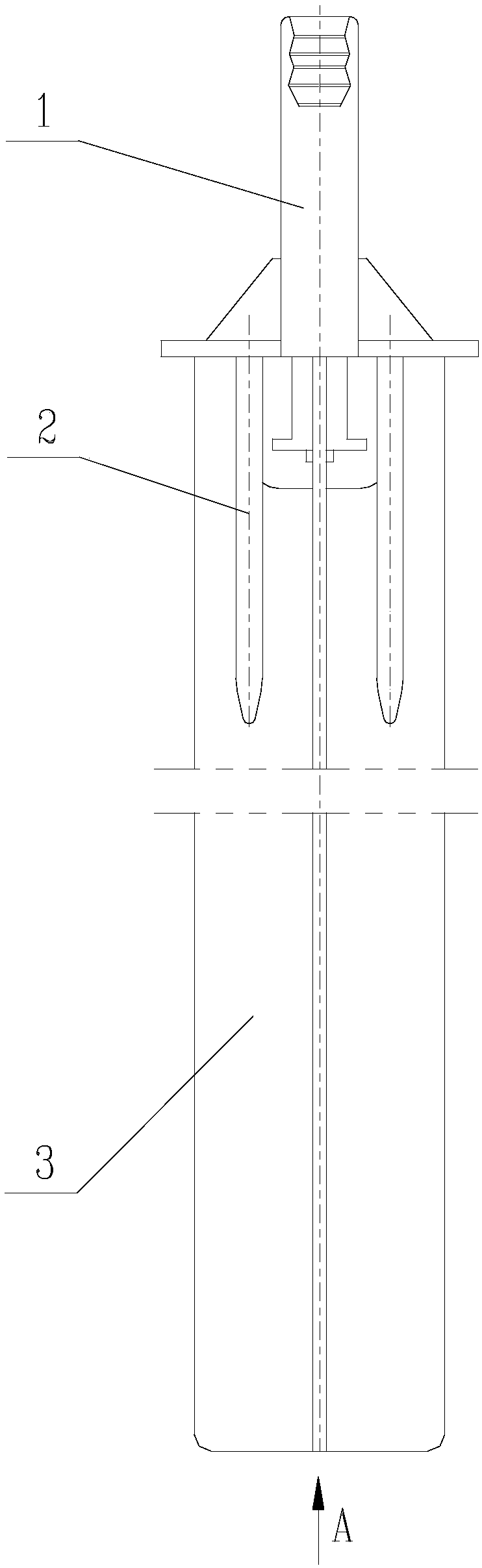
[0049] A control rod assembly and guide assembly structure suitable for supercritical reactors, including a control rod assembly and a guide assembly; wherein, the control rod assembly includes a connecting handle assembly 1 and a cross-shaped control rod 3; the guide assembly includes a guide cylinder and Hydraulic buffer structures6, such as figure 1 and Figure 4 shown. In this embodiment, a buffer rod 2 is added to the connecting handle assembly 1, and the hydraulic buffer structure 6 is optimized at the same time. Through this setting, the sticking phenomenon caused by the deformation of the cross-shaped control rod can be effectively avoided, and the purpose of hydraulic buffering can also be effectively achieved. The specific settings are as follows:
[0050] The buffer rod 2 is arranged in parallel with the cross-shaped control rod 3 . The hydraulic buffer structure 6 includes a cross-shaped control rod channel 601 corresponding to the cross-shaped control rod 3, a ...
Embodiment 2
[0054] The difference between this embodiment and Embodiment 1 is that the structure of the connecting handle assembly 1 is optimized, and the purpose of mechanical buffering is achieved through the optimization of the connecting handle assembly 1 .
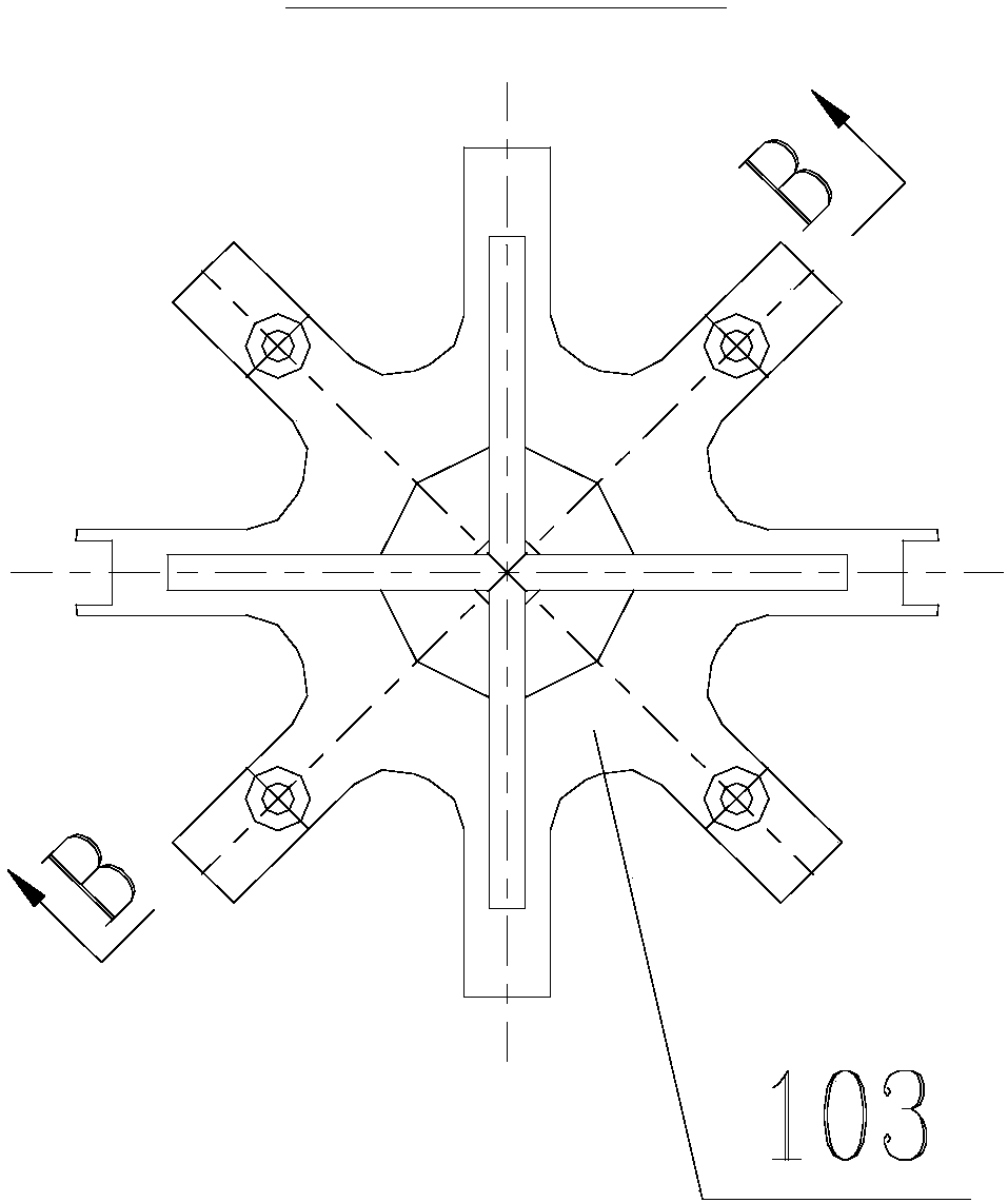
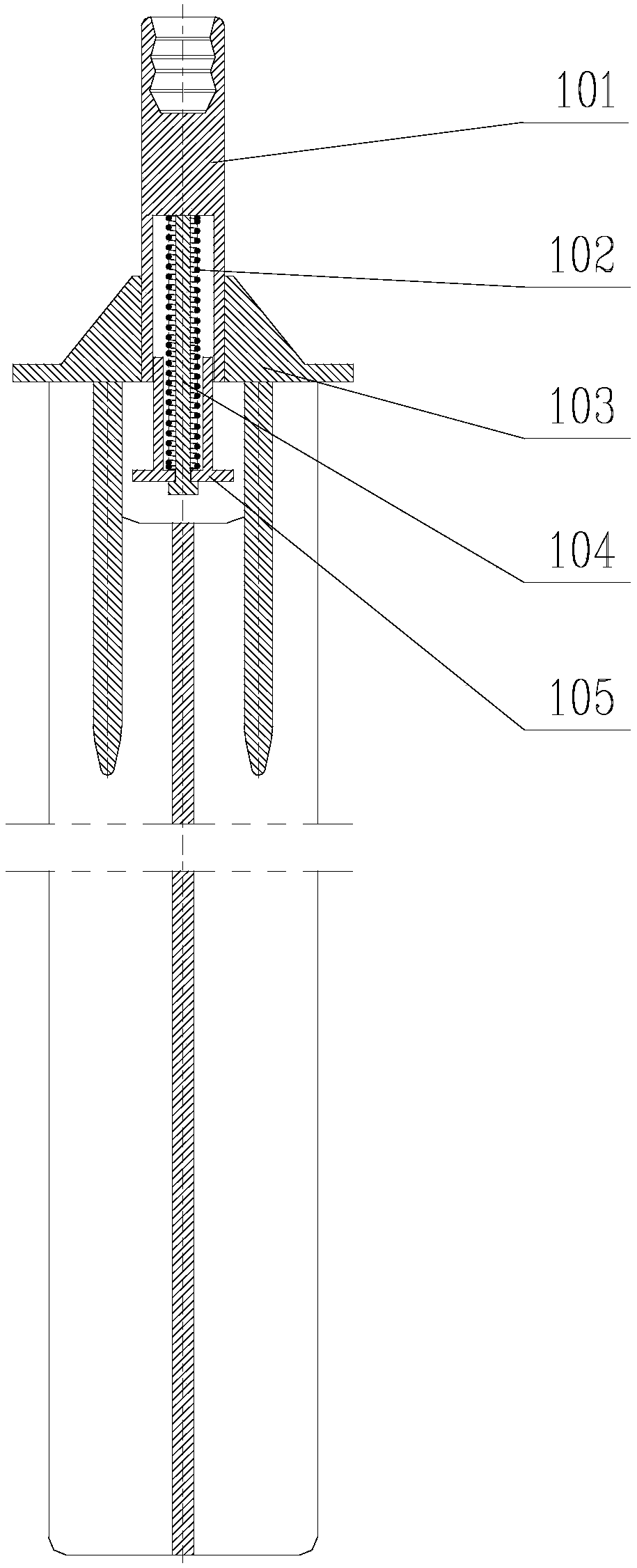
[0055] Such as Figure 1-Figure 3 As shown, the connecting handle assembly 1 includes a connecting sleeve 101 with an internal thread at the top, a star frame 103 fixed on the outer wall of the connecting sleeve 101, a cavity body inside the bottom end of the connecting sleeve 101, and a hollow body arranged in the hollow The guide rod 102 inside the cavity and arranged axially along the connecting sleeve 101, the buffer spring 104 sleeved on the guide rod 102, and the buffer spring 104 sleeved on the guide rod 102 with the bottom end connected to the buffer spring 104 and the top end extending into The buffer piston 105 in the cavity.
[0056] That is, the upper end of the connecting handle assembly 1 is provided with a connect...
Embodiment 3
[0059] The difference between this embodiment and Embodiment 1 is that this embodiment optimizes the structure of the guide cylinder, such as Figure 4-Figure 7 As shown, the guide cylinder includes an upper guide cylinder 4 and a lower guide cylinder 5; the upper guide cylinder is composed of an upper guide cylinder cylinder 401, an upper guide cylinder flange fastener 402, a water hole 403 and an upper guide positioning key 404; The guide cylinder 5 is composed of a lower guide cylinder body 501 , a lower guide cylinder flange fastener 502 and a lower guide positioning key 503 .
[0060] The upper guide cylinder 4 includes an upper guide cylinder body 401, an upper guide cylinder flange fastener 402 arranged at the bottom end of the upper guide cylinder body 401, arranged in the upper guide cylinder body 401 and along the upper guide cylinder body 401 The axially arranged upper guide positioning key 404, and the water flow hole 403 arranged on the upper guide cylinder body 4...
PUM
 Abstract
Description
Claims
Application Information
 - R&D
- Intellectual Property
- Life Sciences
- Materials
- Tech Scout
- Unparalleled Data Quality
- Higher Quality Content
- 60% Fewer Hallucinations
Browse by: Latest US Patents, China's latest patents, Technical Efficacy Thesaurus, Application Domain, Technology Topic, Popular Technical Reports.
© 2025 PatSnap. All rights reserved.Legal|Privacy policy|Modern Slavery Act Transparency Statement|Sitemap|About US| Contact US: help@patsnap.com