
High-efficiency compact aerial radiation field and target scattering testing system

A target scattering and testing system technology, which is applied in the field of high-efficiency compact antenna radiation field and target scattering test system, can solve the problems of large test distance, high construction cost, and low efficiency of single-reflection surface compact field quiet zone, and achieve reduction Engineering difficulty, the effect of eliminating edge diffraction

Inactive Publication Date: 2018-01-19
西安普腾电子科技有限公司
View PDF6 Cites 12 Cited by
  • Summary
  • Abstract
  • Description
  • Claims
  • Application Information

AI Technical Summary

Problems solved by technology

[0004] When the frequency reaches millimeter wave or even submillimeter wave, when constructing the antenna radiation test far field, the test distance is large, the site cost is high, and the construction cost is high;
[0005] The compact field test system can effectively solve the problem of large venues, but the efficiency of the traditional single reflector compact field quiet zone is low, and it is necessary to further improve the efficiency of the single reflector compact field quiet zone

Method used


Image

  • High-efficiency compact aerial radiation field and target scattering testing system
  • High-efficiency compact aerial radiation field and target scattering testing system

Examples


Embodiment Construction

[0022] In order to make the object, technical solution and advantages of the present invention more clear, the present invention will be further described in detail below in conjunction with the examples. It should be understood that the specific embodiments described here are only used to explain the present invention, not to limit the present invention.

[0023] The application principle of the present invention will be described in detail below in conjunction with the accompanying drawings.

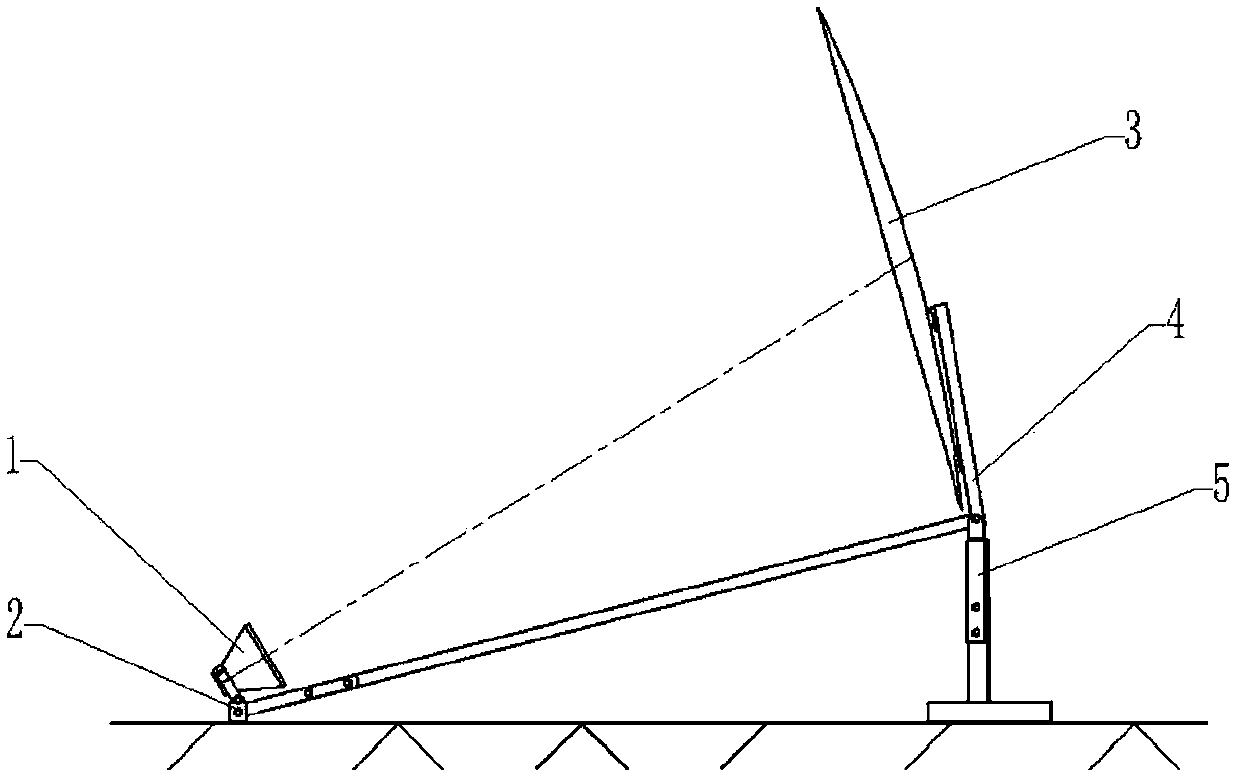
[0024] Such as figure 1 As shown, the high-efficiency compact antenna radiation field and target scattering test system provided by the embodiment of the present invention includes: a high-efficiency compact field feed source 1, a high-efficiency compact field feed source and a fixing bracket 2 for the reflecting surface, a shaped reflecting surface 3, Shaped reflection surface back support 4, reflection surface angle adjustment support 5 from the ground.

[0025] The high-efficiency...


PUM


Abstract

The invention belongs to the technical field of centimeter-wave, millimeter-wave and submillimeter-wave high-efficiency compact aerial radiation field and target scattering testing systems, and discloses a high-efficiency compact aerial radiation field and target scattering testing system. The system comprises a high-efficiency compact field feed source. The high-efficiency compact field feed source is disposed on a fixed support. A forming reflection plane back support and a reflection plane off-ground angle adjustment support are connected together, and a forming reflection plane is installed on the forming reflection plane back support. The fixed support is connected with the forming reflection plane back support and the reflection plane off-ground angle adjustment support through a connecting rod. The system can remove nonuniform characteristics of a dead zone caused by an edge diffraction field of the reflection plane more effectively. Furthermore, the system reduces the level fluctuation of the dead zone.

Description

technical field [0001] The invention belongs to the technical field of centimeter wave, millimeter wave and submillimeter wave compact antenna radiation field and target scattering test system, and in particular relates to a high-efficiency compact antenna radiation field and target scattering test system. Background technique [0002] With the rapid development of centimeter wave, millimeter wave and submillimeter wave technologies, the demand for millimeter wave and submillimeter wave antenna testing and the testing of scattering parameters of various targets in millimeter wave and submillimeter wave frequency bands are becoming increasingly urgent. The antenna radiation field test can be divided into far-field test and near-field test. The far-field test is to directly measure the far-field characteristics of the antenna after a certain test distance is met, while the near-field test is to measure the near-field data of the antenna under test, and then The far-field chara...

Claims


Application Information

Patent Timeline
IPC IPC(8): H01Q19/13H01Q21/00
Inventor 张梅
Owner 西安普腾电子科技有限公司
Learn More