
Wide angle automobile front headlamp

A technology of automobile headlights and automobiles, which is applied in the direction of headlights, lampshades, motor vehicles, etc., can solve problems such as limitation of irradiation angle, achieve the effects of improving impact performance, wide lighting range, and improving lighting performance

Inactive Publication Date: 2018-01-19
芜湖晶鑫光电照明有限公司
View PDF5 Cites 0 Cited by
  • Summary
  • Abstract
  • Description
  • Claims
  • Application Information

AI Technical Summary

Problems solved by technology

The lighting lamp of this patent is still a planar structure, so it is limited in the irradiation angle

Method used


Image

  • Wide angle automobile front headlamp
  • Wide angle automobile front headlamp
  • Wide angle automobile front headlamp

Examples


Embodiment 1

[0017] Preferred embodiments of the present invention will be described in detail below in conjunction with the accompanying drawings.

specific Embodiment approach

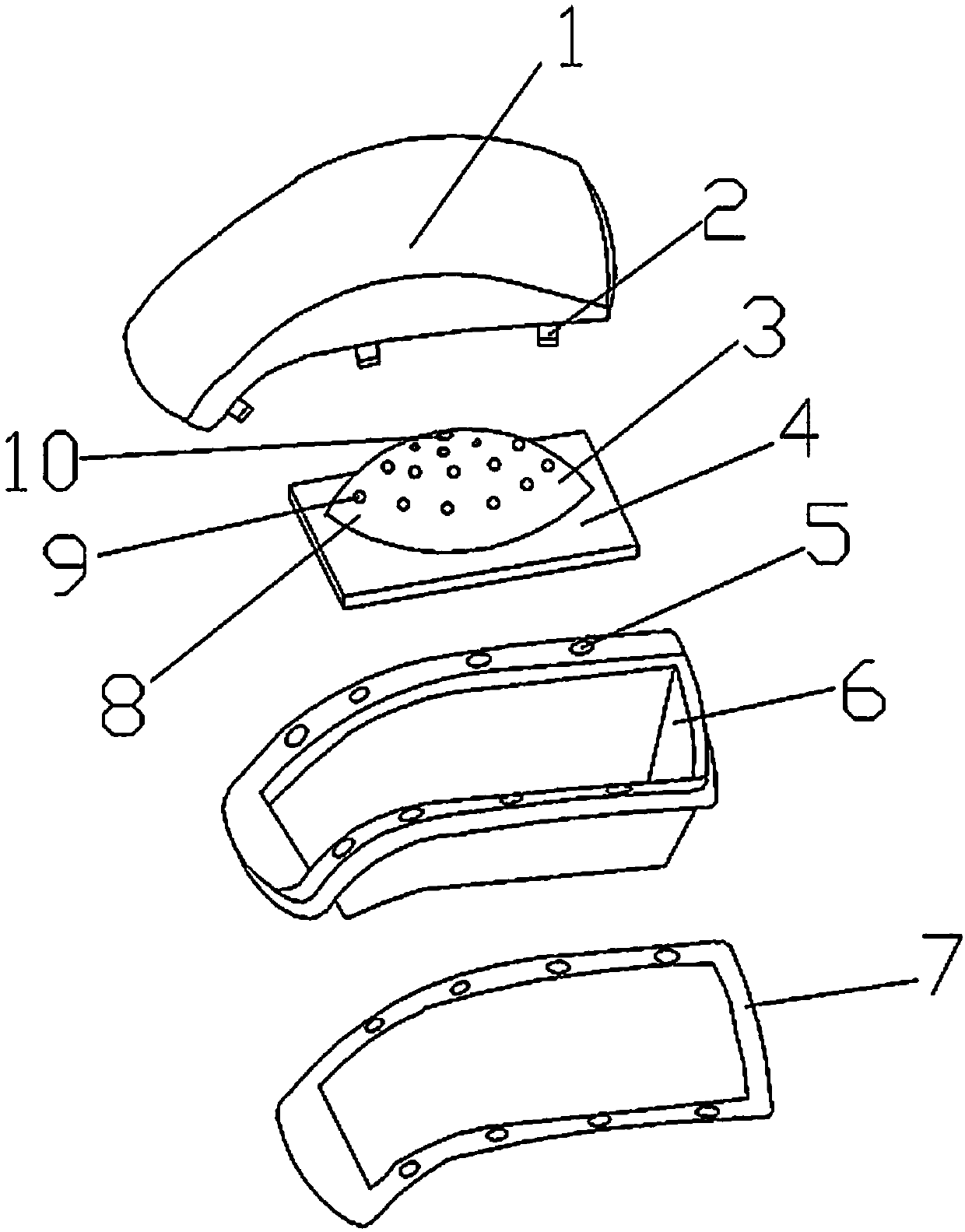
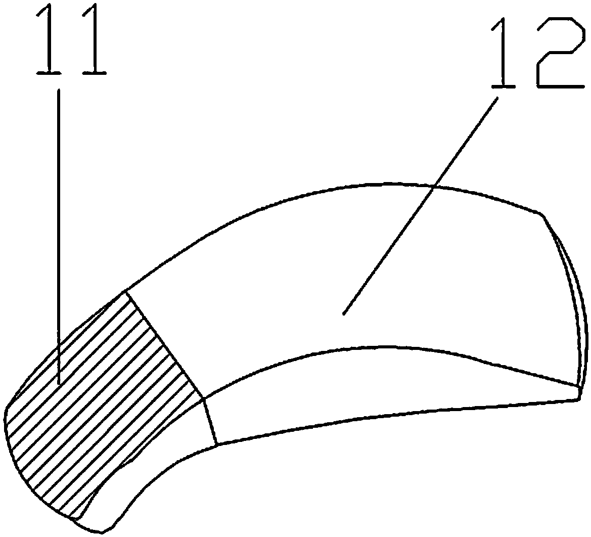
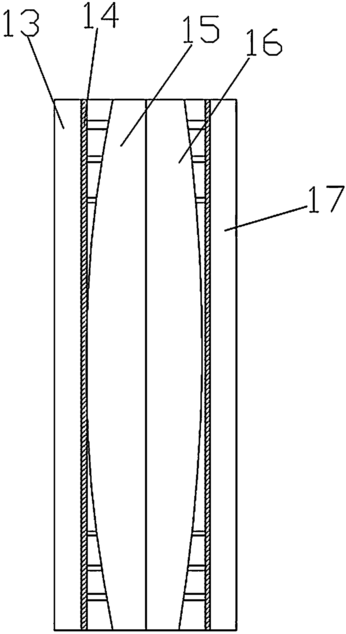
[0018] Figure 1-3 Show the specific embodiment of the present invention: a kind of wide-angle automobile headlamp, comprise automobile lampshade 1, mounting buckle 2, spherical light board 3, mounting plate 4, mounting hole 5, mounting groove 6 and rubber washer 7, several mounting buckles 2 Fixedly arranged on both sides of the automobile lampshade 1, the spherical lamp board 3 is fixedly arranged on the installation plate 4, the installation plate 4 is embedded in the installation groove 6, and several installation holes 5 are evenly arranged on both sides of the installation groove 6. Rubber The gasket 7 is nested on the installation groove 6 and is located below the edge of the installation groove 6. The spherical lamp panel 3 includes a spherical panel 8, an illumination LED lamp 9 and a cooling hole 10. The spherical panel 8 is fixedly arranged on the installation panel 4. Several The lighting LED lamps 9 are evenly arranged on the spherical plate 8, and the heat dissip...

Embodiment 2

[0022] Preferred embodiments of the present invention will be described in detail below in conjunction with the accompanying drawings.

[0023] Figure 1-2 Show the specific embodiment of the present invention: a kind of wide-angle automobile headlamp, comprise automobile lampshade 1, mounting buckle 2, spherical light board 3, mounting plate 4, mounting hole 5, mounting groove 6 and rubber washer 7, several mounting buckles 2 Fixedly arranged on both sides of the automobile lampshade 1, the spherical lamp board 3 is fixedly arranged on the installation plate 4, the installation plate 4 is embedded in the installation groove 6, and several installation holes 5 are evenly arranged on both sides of the installation groove 6. Rubber The gasket 7 is nested on the installation groove 6 and is located below the edge of the installation groove 6. The spherical lamp panel 3 includes a spherical panel 8, an illumination LED lamp 9 and a cooling hole 10. The spherical panel 8 is fixedly...


PUM


Abstract

The invention discloses a wide angle automobile front headlamp. The wide angle automobile front headlamp comprises an automobile lampshade, mounting buckles, a spherical lamp plate, a mounting plate,mounting holes, a mounting groove and a rubber gasket. The multiple mounting buckles are fixed on the two sides of the automobile lampshade. The spherical lamp plate is fixed on the mounting plate. The mounting plate is embedded in the mounting groove. The multiple mounting holes are evenly formed in the edges of the two sides of the mounting groove. The rubber gasket is embedded in the mounting groove in a sleeving mode and located on the lower portion of the edge of the mounting groove. The spherical lamp plate comprises a spherical plate, illuminating LED lamps and a heat dissipation hole.The spherical plate is fixedly arranged on the mounting plate. The multiple illuminating LED lamps are arranged evenly on the spherical plate. The heat dissipation hole is formed in the center of thespherical plate. According to the wide angle automobile front headlamp, through the spherical lamp plate, the lighting angle of lighting of the automobile front headlamp can be enlarged, so that an automobile has a wider lighting range, and the lighting performance of the automobile headlamp is improved.

Description

technical field [0001] The invention relates to the field of automobile lamps, in particular to a wide-angle automobile headlight. Background technique [0002] Car headlights are installed in the front of the car, and the general car headlights are planar structures, so when illuminating, they can only directly illuminate the range in front of the car, causing the problem that the lighting range of the car is narrow. [0003] Similar to patent CN201621350226.5, the utility model discloses a heat-dissipating car lamp, which includes a base for fixed connection with the car body, a circuit board and a lighting lamp arranged in the base, and a The heat dissipation fan for the circuit board and the lighting lamp, and the transparent cover that covers the surface of the base. The accommodating cavity, a partition plate is provided between the first accommodating cavity and the second accommodating cavity, and a vent hole communicating with the first accommodating cavity and the...

Claims


Application Information

Patent Timeline
Patent Type & Authority Applications(China)
IPC IPC(8): F21S41/25F21V29/83F21V3/04F21W107/10F21Y115/10
Inventor 祖骅
Owner 芜湖晶鑫光电照明有限公司
Learn More