
Electronic equipment and preamble signal generation, transmission, reception method and device

A leading signal and receiving end technology, applied in the field of signal processing, can solve the problems of large error and peak platform problem, achieve the effect of obvious peak, small timing error, and avoid timing ambiguity

Active Publication Date: 2020-09-08
SHANGHAI ADVANCED RES INST CHINESE ACADEMY OF SCI
View PDF10 Cites 0 Cited by
  • Summary
  • Abstract
  • Description
  • Claims
  • Application Information

AI Technical Summary

Problems solved by technology

[0009] However, in the process of synchronizing by using the cyclically repeated OFDM coincidence or m-sequence as the autocorrelation operation of the preamble signal, there will be a continuous peak, which lasts until one symbol length before the start of the data segment of the preamble signal
Therefore, when using this scheme, the timing position can be determined according to the falling edge of the peak platform. However, due to the multipath characteristics of the channel and the influence of noise, the error in detecting the falling edge of the peak platform will be large
[0010] In order to overcome the peak platform problem caused by the structure of the directly repeated cascaded preamble signal in the autocorrelation operation, a preamble signal structure quoted in DVB-T2 (the second generation European digital terrestrial television broadcasting transmission standard) is proposed

Method used


Image

  • Electronic equipment and preamble signal generation, transmission, reception method and device
  • Electronic equipment and preamble signal generation, transmission, reception method and device
  • Electronic equipment and preamble signal generation, transmission, reception method and device

Examples


Embodiment Construction

[0065] The following describes the implementation of the present invention through specific specific examples. Those skilled in the art can easily understand other advantages and effects of the present invention from the content disclosed in this specification. The present invention can also be implemented or applied through other different specific embodiments, and various details in this specification can also be modified or changed based on different viewpoints and applications without departing from the spirit of the present invention. It should be noted that the following embodiments and the features in the embodiments can be combined with each other if there is no conflict.

[0066] It should be noted that the illustrations provided in the following embodiments only illustrate the basic idea of ​​the present invention in a schematic way, so the figures only show the components related to the present invention instead of the actual implementation of the number, shape and For...


PUM


Abstract

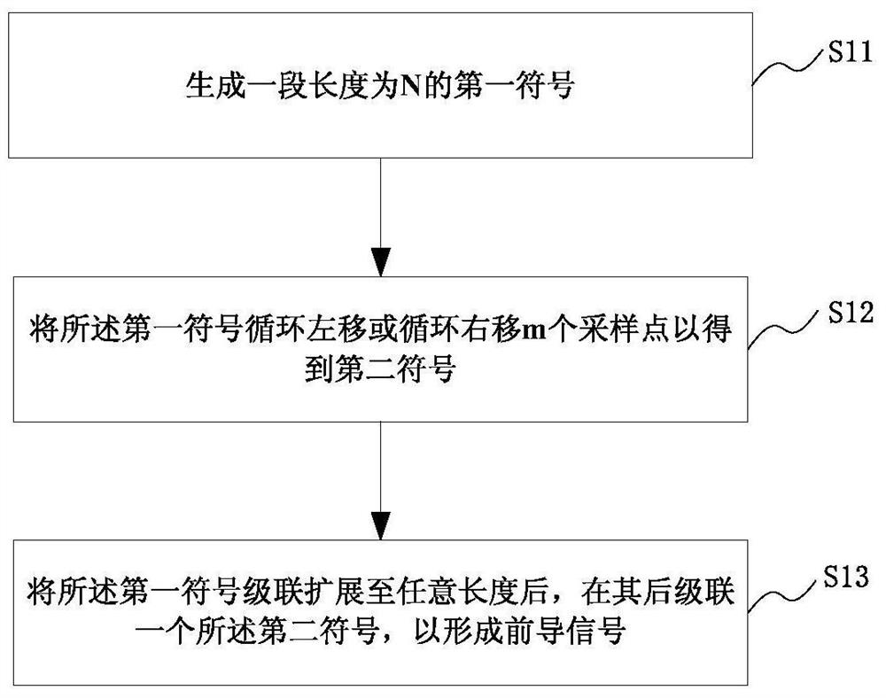
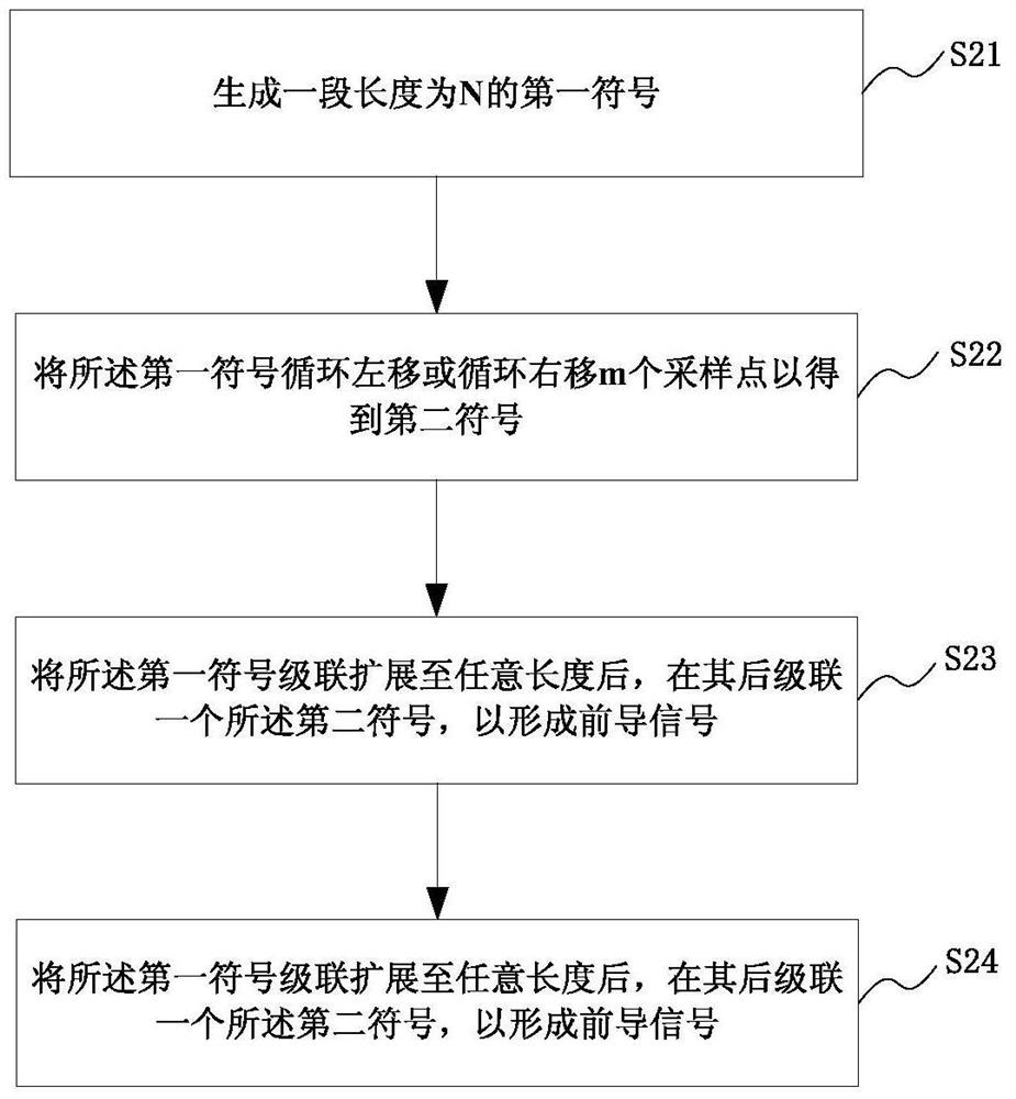
The invention provides electronic equipment, and a pilot signal forming, sending and receiving method and device; the method comprises the following steps: forming a first symbol and a second symbol with the length as N, wherein the second symbol is obtained by rotating left or right the first symbol by m sampling points; cascading and expanding the first symbol to a random length, and cascading asecond symbol behind, thus forming the pilot signal. The autocorrelation energy value initial portion will form a peak value under random access conditions, and whether a detection signal exists or not can be determined by comparing the peak value with a set threshold, thus shortening the detection time; secondly, in the timed estimation aspect, an obvious peak value can be formed by carrying outdual autocorrelation operation in a receiver, so timed estimation is carried out according to the peak value position, thus preventing timed fuzzy caused by a peak value platform in a conventional mode; the method can provide more obvious peak value, is small in timed error, thus improving the timed estimation performance.

Description

Technical field [0001] The present invention relates to the field of signal processing, and in particular to an electronic device and a method and device for generating, sending and receiving a preamble signal. Background technique [0002] In wireless networks such as self-organizing networks, before the initial link is established, the two parties in communication do not know the frequency of signal transmission. At this time, the sender generally sends a paging preamble signal at its working frequency first, so that the receiver can complete the capture of the paging preamble signal within a certain capture time window. The acquisition time window is generally much smaller than the length of the paging preamble signal to ensure that the receiving end can make the acquisition time window within the duration of the paging preamble signal when traversing and searching multiple different frequency points. Since the frequency point used by the paging preamble signal to be captured...

Claims


Application Information

Patent Timeline
Patent Type & Authority Patents(China)
IPC IPC(8): H04L27/26H04L7/00
Inventor 李明齐张想张身志
Owner SHANGHAI ADVANCED RES INST CHINESE ACADEMY OF SCI
Learn More