
A Compensation Method for Timing Time

A technology of timing time and compensation method, applied in electronic timers, automatic power control, clocks driven by synchronous motors, etc. Achieve the effect of eliminating crystal oscillator error, small timing error and increasing accuracy

Active Publication Date: 2017-11-17
SHENZHEN ZHENBANG TECH
View PDF5 Cites 0 Cited by
  • Summary
  • Abstract
  • Description
  • Claims
  • Application Information

AI Technical Summary

Problems solved by technology

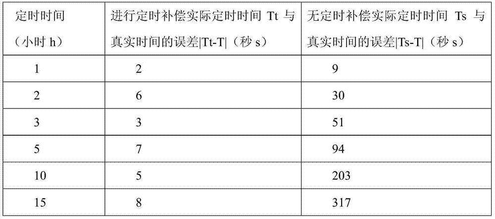
[0003] At present, electronic products involving timing functions often have low accuracy and large errors due to the small time error of the crystal oscillator of the main control chip and the many functions that the main control chip has to handle. ; Especially when the timing time reaches more than 10 hours, the error becomes more obvious
[0004] That is to say, the electronic products with timing function on the market now have the following defects: (1) the timing time is greatly affected by the crystal oscillator of the main control chip; (2) when the timing time is too long, the longer the timing time, the accumulated The greater the error is, the farther it is from the real value of the timing time; (3) the timing time is greatly affected by the amount of program processed by the master control chip, and the larger the amount of program processed by the master control chip, the greater the error of the timing time

Method used


Image

  • A Compensation Method for Timing Time
  • A Compensation Method for Timing Time

Examples


Embodiment 1

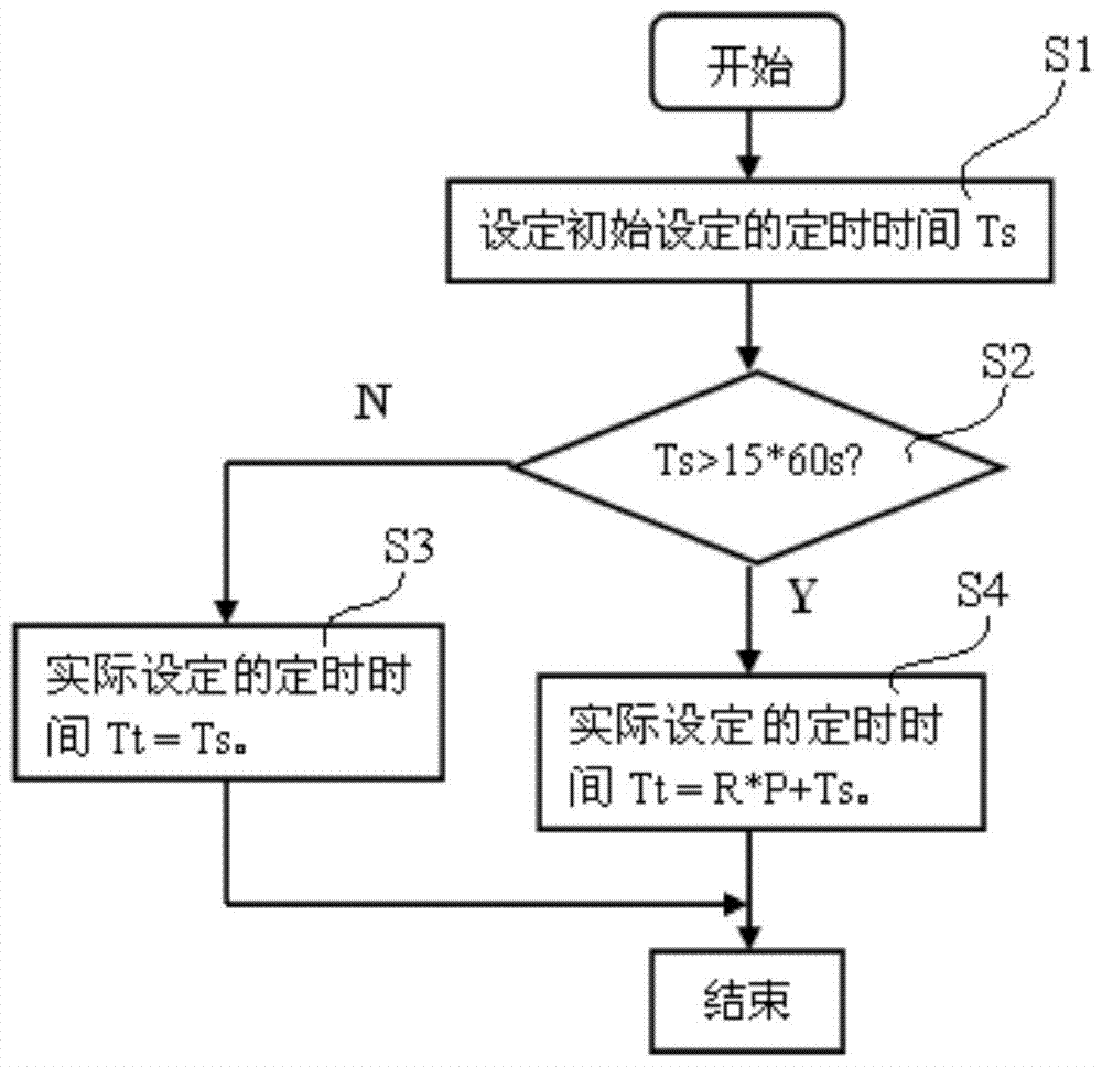
[0028] Such as figure 1 As shown, this example provides a timing compensation method, including the following compensation steps:

[0029] Step S1, input the initial set timing time Ts;

[0030] Step S2, judging whether the initially set timing time Ts is greater than the timing time constant Tu, the timing time constant Tu is a timing time period set by the user, if not, jump to step S3, if so, jump to step S4 ;

[0031] Step S3, limiting the actual set timing time Tt=initially set timing time Ts;

[0032] Step S4, define the actual set timing time Tt=R*P+Ts, wherein, the P is the number of equal parts, and the P is an integer value obtained after dividing the initially set timing time Ts by the timing time constant Tu ; The R is the compensation time, and the compensation time is the difference between the timing time constant Tu and the actual timing time within the same timing period.

[0033] Described timing time constant Tu is a timing time cycle that user defines, ...

Embodiment 2

[0050] On the basis of Embodiment 1, after the compensation time is calculated in this example, the timing time is compensated every time a timing period corresponding to the timing time constant Tu passes. That is, assuming that the timing time constant Tu is 15 minutes, then, after every 15 minutes, the timing time is compensated once.

[0051] In this example, after the timing time is compensated each time, the compensated timing time is used as the new initial setting timing time Ts', and the new initial setting timing time Ts'=R+Ts-Tu, and then set Set the new initially set timing time Ts' as the initially set timing time Ts, and then implement the compensation process from step S1 to step S4 for the new initially set timing time Ts'.

[0052] That is to say, if the timing time constant Tu is 15 minutes, then after every 15 minutes, the timing time is compensated once, and then the compensated timing time is used as the timing time Ts' of the new initial setting, so that ...


PUM


Abstract

The invention provides a timing time compensation method. The timing time compensation method comprises the following compensation steps of: S1, inputting an initially-set timing time Ts; S2, judging whether the initially-set timing time Ts is greater than a timing time constant Tu; if not, skipping to a step S3; if yes, skipping to a step S4; S3, defining an actually-set timing time Tt to be equal to the initially-set timing time Ts; and S4, defining the actually-set timing time Tt to be equal to R*P+Ts, wherein P represents for an integer value obtained by dividing the initially-set timing time Ts by the timing time constant Tu and rounding, R represents for compensation time, and the compensation time is a difference value between the timing time constant Tu and the actually-set timing time Tt in the same timing time period. By virtue of the present invention, the crystal vibration errors can be basically eliminated, thereby ensuring that the difference value between the timing time and the actually-set timing time is not increased when the timing time is prolonged; the accuracy of the timing time is improved; the errors are reduced.

Description

technical field [0001] The invention relates to a time compensation method, in particular to a timing compensation method suitable for electronic products with a timing function. Background technique [0002] The timing function is often used in many household appliances, such as air conditioners, refrigerators, washing machines, and rice cookers, etc., and the timing time is often used to control the power on and off; therefore, the accuracy of the timing time has become an important factor in the current technology development, especially In some medical electronic products, the accuracy of timing is required to be higher. [0003] At present, electronic products involving timing functions often have low accuracy and large errors due to the small time error of the crystal oscillator of the main control chip and the many functions that the main control chip has to handle. ; Especially when the timing reaches more than 10 hours, the error becomes more obvious. [0004] Tha...

Claims


Application Information

Patent Timeline
Patent Type & Authority Patents(China)
IPC IPC(8): H03L7/08H03L7/081G04G7/00
CPCG04G7/00H03L7/0805H03L7/0812
Inventor 柯忠乘陈志杰
Owner SHENZHEN ZHENBANG TECH
Learn More