Eureka AIR delivers breakthrough ideas for toughest innovation challenges, trusted by R&D personnel around the world.

Magnetic levitation barrier gate

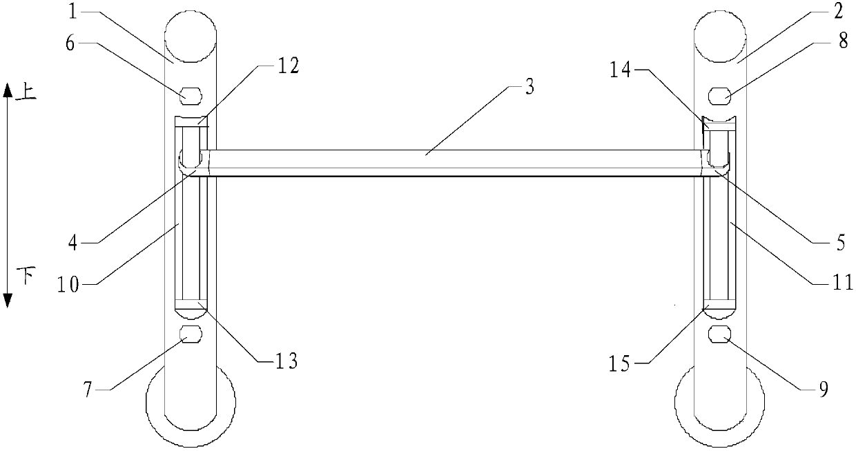
A magnetic levitation and barrier gate technology, which is applied to roads, roads, magnetic attraction or thrust holding devices, etc., can solve problems such as insufficient rise, barrier gate pole accidentally smashing vehicles, inaccurate detection and driving, etc., to achieve stable control and drive precise effect

Pending Publication Date: 2018-01-09
北京欣恒宇伟业科技有限公司
View PDF6 Cites 4 Cited by
  • Summary
  • Abstract
  • Description
  • Claims
  • Application Information

AI Technical Summary

Problems solved by technology

[0003] In the daily use of traditional barriers, one end of the barrier lever is used as a shaft, and the other end is relatively rotated to achieve lifting. Due to the continuous passage of many vehicles, the detection and drive of the barrier gate when controlling the lift of the barrier lever will be inaccurate. At this time, it is easy to happen that the barricade pole will fall when it is raised to a high place and hit the vehicle by mistake, and the rise will not be in place, and the vehicle will not be able to pass and other bad phenomena.

Method used


Image

  • Magnetic levitation barrier gate

Examples


Embodiment approach 2

[0035] Considering that the blocking and release of vehicles can be realized conveniently and effectively, the present invention proposes two specific implementation modes: Embodiment 1: the bottom end of the first chute 10 and the bottom end of the second chute 11 The distance from the end to the ground is 1m to 1.5m, which can ensure that the two ends of the cross bar 3 are located at the bottom of the first chute 10 and the second chute 11 to effectively block the vehicle. When it needs to be released, the cross bar 3 will rise through the magnetic force At the top of the first chute 10 and the second chute 11, the vehicle can pass directly under the cross bar 3, which can conveniently and effectively block and release the vehicle. Embodiment 2: The bottom end of the first chute 10 and the bottom end of the second chute 11 are flush with the ground, so as to ensure that the two ends of the cross bar 3 are located in the first chute 10 and the second chute 11 When it is on t...


PUM


Abstract

The invention relates to a magnetic levitation barrier gate comprising a first vertical column, a second vertical column and a transverse rod. The first vertical column and the second vertical columnare vertically arranged and mutually parallel; the two ends of the transverse rod are arranged on the first vertical column and the second vertical column correspondingly and can slide up and down along the first vertical column and the second vertical column; a first magnetic piece and a second magnetic piece are arranged at the two ends of the transverse rod; a first electromagnet is arranged onthe upper portion of the first vertical column, and a second electromagnet is arranged on the lower portion of the first vertical column; a third electromagnet is arranged on the upper portion of thesecond vertical column, and a fourth electromagnet is arranged on the lower portion of the second vertical column; and the transverse rod slides upwards along the first vertical column and the secondvertical column through attraction of the first magnetic piece and the first electromagnet, repulsion of the first magnetic piece and the second electromagnet, attraction of the second magnetic pieceand the third electromagnet and repulsion of the second magnetic piece and the fourth electromagnet, and slides downwards along the first vertical column and the second vertical column through repulsion of the first magnetic piece and the first electromagnet, attraction of the first magnetic piece and the second electromagnet, repulsion of the second magnetic piece and the third electromagnet andattraction of the second magnetic piece and the fourth electromagnet. According to the magnetic levitation barrier gate, up and down displacement of the transverse rod of the barrier gate can be achieved through electromagnetic control, and the situation that a vehicle collides the rod is effectively avoided.

Description

technical field [0001] The invention relates to the technical field of an access gate, in particular to a magnetic levitation gate. Background technique [0002] Barrier gates, also known as car stoppers, are passage entrance and exit management equipment specially used to restrict motor vehicles on the road. They are now widely used in highway toll stations and parking lot systems to manage vehicle passages and to manage vehicle entry and exit. [0003] In the daily use of traditional barriers, one end of the barrier lever is used as a shaft, and the other end is relatively rotated to achieve lifting. Due to the continuous passage of many vehicles, the detection and drive of the barrier gate when controlling the lift of the barrier lever will be inaccurate. At this time, it is easy to happen that the barrier pole will fall when it is raised to a high place and hit the vehicle by mistake, and it will not rise in place, and the vehicle cannot pass through. Contents of the i...

Claims


Application Information

Patent Timeline
IPC IPC(8): E01F13/04H02N15/00
Inventor 张诗红
Owner 北京欣恒宇伟业科技有限公司
Why Eureka
Eureka Blog
Learn More