
Method for maximizing electrical damping, damping controller and applications

A technology of electrical damping and current, applied in the direction of synchronous generator control, control of generators through magnetic field changes, flexible AC transmission systems, etc.

Inactive Publication Date: 2017-12-22
CHINA SOUTHERN POWER GRID COMPANY +1
View PDF4 Cites 1 Cited by
  • Summary
  • Abstract
  • Description
  • Claims
  • Application Information

AI Technical Summary

Problems solved by technology

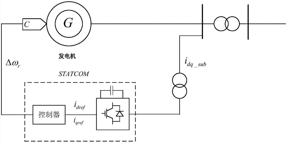
[0006] Aiming at the above defects or improvement needs of the prior art, the present invention provides a method for providing maximum electrical damping, a damping controller and its application, thereby solving the problem that active and reactive currents are not involved in the technique of applying STATCOM to suppress subsynchronous oscillations How to optimize the configuration and provide the technical problem of maximizing electrical damping

Method used


Image

  • Method for maximizing electrical damping, damping controller and applications
  • Method for maximizing electrical damping, damping controller and applications
  • Method for maximizing electrical damping, damping controller and applications

Examples


Embodiment Construction

[0051] In order to make the object, technical solution and advantages of the present invention clearer, the present invention will be further described in detail below in conjunction with the accompanying drawings and embodiments. It should be understood that the specific embodiments described here are only used to explain the present invention, not to limit the present invention. In addition, the technical features involved in the various embodiments of the present invention described below can be combined with each other as long as they do not constitute a conflict with each other.

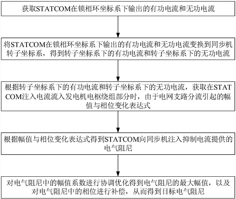
[0052] Such as figure 1 Shown is a schematic flow chart of a method for maximizing electrical damping provided by an embodiment of the present invention. figure 1 The method shown includes the following steps:

[0053] (1) Obtain the active current output by STATCOM in the phase-locked loop coordinate system and reactive current

[0054] (2) Will and Transform to the rotor coordinate ...


PUM


Abstract

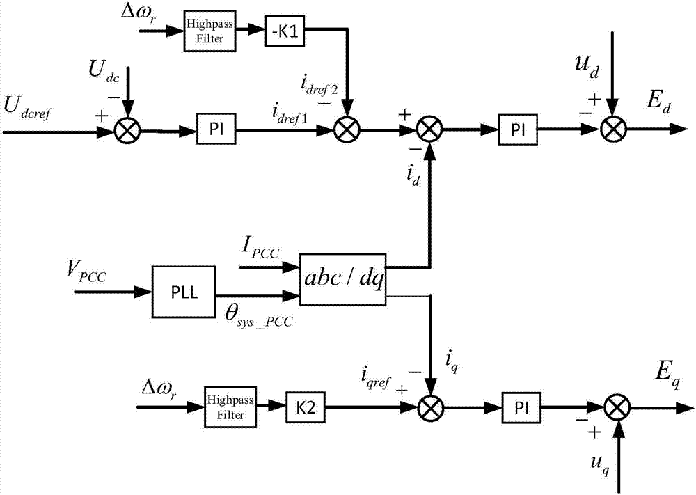
The invention discloses a method for maximizing electrical damping, a damping controller and applications, and belongs to the field of power system stability control. The method comprises the following steps: acquiring active current i[d] and reactive current i[q] output by a STATCOM in a phase-locked loop coordinate system; transforming the active current i[d] and the reactive current i[q] to obtain active current i<s>[d] and reactive current i<s>[q] in the rotor coordinate system; and according to the active current i<s>[d] and the reactive current i<s>[q], when STATCOM injection current flows into a generator, obtaining the amplitude and phase change expressions caused by the branch of apower grid; according to the amplitude and phase change expression, obtaining electrical damping when STATCOM injects suppression current to asynchronous machine; and obtaining the maximum amplitude of the electrical damping and compensating the phase in the electrical damping to obtain the target electrical damping. By taking full advantage of the limited capacity of STATCOM, the cost is reduced, the maximum electrical damping is provided, and the subsynchronous resonance caused by the series compensation connection of the thermal power generating unit and the power grid is well suppressed.

Description

technical field [0001] The invention belongs to the technical field of power system stability control, and more specifically relates to a method for suppressing subsynchronous resonance and maximizing electrical damping by using a static synchronous compensator STATCOM active and reactive dual-channel coordinated control, a damping controller and its application. Background technique [0002] With the construction of large-scale thermal power bases in my country and the formation of the west-to-east power grid pattern, large-scale long-distance power transmission has become an inevitable trend, and high-voltage and ultra-high-voltage AC transmission channels equipped with series compensation devices will become one of the important choices for future power transmission channels one. However, when a large thermal power unit is connected to an AC line with a series compensation device, subsynchronous resonance is very likely to occur, which threatens the safety of thermal power...

Claims


Application Information

Patent Timeline
Patent Type & Authority Applications(China)
IPC IPC(8): H02J3/24H02P9/14H02P103/20
CPCH02J3/24H02P9/14H02P2103/20Y02E40/10
Inventor 刘洪涛赵化时王龙飞陈家乐高红亮周华锋朱建行侯佳佐万民惠
Owner CHINA SOUTHERN POWER GRID COMPANY
Learn More