Radiation inspection system

A technology of inspection system and radiation device, applied in the field of radiation inspection, to achieve the effect of improving quality and reducing height and size

Active Publication Date: 2017-12-15
พาวเวอร์สแกน ไฮเทค โค แอลทีดี
View PDF10 Cites 6 Cited by
  • Summary
  • Abstract
  • Description
  • Claims
  • Application Information

AI Technical Summary

Problems solved by technology

The current vehicle inspection system needs to set up a separate detection channel for the vehicles that drive through the scan, which takes up extra space

Method used


Image

  • Radiation inspection system
  • Radiation inspection system
  • Radiation inspection system

Examples


Embodiment 1

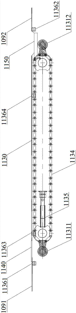
[0132] see Figure 10-Figure 13 ,in Figure 10 It is a front view showing that the radiation inspection system built by the present invention drags and scans the vehicle; Figure 10A yes Figure 10 The enlarged schematic diagram of the part of the dragging device in ; Figure 11 It is a front view showing the drive-through scanning of the vehicle by the radiation inspection system built by the present invention; Figure 11A yes Figure 11 The enlarged schematic diagram of the part of dragging device in ; Figure 12 is a side view; Figure 13 is a top view.

[0133] The rack 100 can be built on the chassis 1001 . The frame 100 can include a left column frame and a right column frame, perpendicular to the chassis 1001 upper surface. The lower ends of the left column frame and the right column frame are respectively connected with the left and right sides of the chassis 1001, and the upper ends are respectively connected with the left and right sides of the beam frame. Th...

Embodiment 2

[0180] see Figure 14-Figure 17 ,in Figure 14 It is a front view showing that the radiation inspection system built by the present invention drags and scans the vehicle; Figure 15 It is a front view showing the drive-through scanning of the vehicle by the radiation inspection system built by the present invention; Figure 16 is a side view; Figure 17 is a top view.

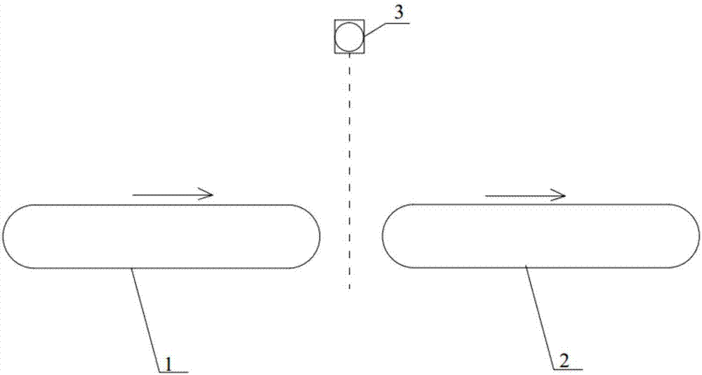
[0181] Different from Embodiment 1, the radiation inspection system in this embodiment adopts bilateral dragging devices, that is, a dragging device is provided on both sides of the radiation inspection channel. Moreover, the dragging device is a chain plate / flat dragging device. Only the differences are described below, and for the same parts, please refer to the related description above.

[0182] As shown in the figure, the first dragging device 213 and the second dragging device 214 are both single-stage flat plate / chain plate conveyor structures, installed on both sides of the radiation inspection ch...


PUM


Abstract

The invention discloses a radiation inspection system, which is characterized in that a radiation device is arranged at the bottom of a radiation inspection channel and used for emitting scanning ray beams to a detection area; one or more detectors is / are arranged at the top and / or the lateral of the radiation inspection channel and used for receiving imaging ray beams which are transmitted or scattered from a detected object in the detection area; a dragging device is arranged at one side or both sides in the radiation inspection channel and used for dragging the detected object to travel along the traveling direction; and a control device controls the radiation device to emit the scanning ray beams to the detection area in a first operation mode under a condition that the detected object passes the radiation inspection channel under a driving effect of its own, and controls the radiation device to emit scanning ray beams to the detection area in a second operation mode under a condition that the detected object passes the radiation inspection channel under a dragging effect of the dragging device. Therefore, the quality of formed images can be improved, the height of the overall radiation inspection system is reduced, and dual-mode scanning is achieved.

Description

technical field [0001] The invention relates to the field of radiation inspection, in particular to a radiation inspection system. Background technique [0002] The inspection system for small and medium-sized passenger vehicles is divided into drag scanning mode and drive-through scanning mode. In the drag scanning mode, when the inspected vehicle reaches a specific position, the driver and passengers need to get off, and then the conveying device will transport the inspected vehicle from the entrance to the exit of the scanning channel. When passing through the scanning area, the vehicle is transported to At a specific location, the control system controls the radiation source to emit rays to scan the vehicle. In drive-through scan mode, the driver drives the vehicle through the scan lane. [0003] At present, whether it is drag scanning mode or drive-through scanning mode, the radiation source is basically placed on the top of the scanning channel, and the ray scans and...

Claims


Application Information

Patent Timeline
IPC IPC(8): G01V5/00
CPCG01V5/22
Inventor 闫雄王少锋刘铮冯志涛王春雷
Owner พาวเวอร์สแกน ไฮเทค โค แอลทีดี
Why Eureka
Try Eureka