
Wireless monitoring system and method

A wireless monitoring and monitoring center technology, applied in the transmission system, signal transmission system, digital transmission system, etc., can solve the problems of complex wiring engineering, poor scalability, difficult wiring, etc., to achieve good system scalability, short project cycle, good The effect of mobility

Pending Publication Date: 2017-12-08
北京中天鼎盛视讯科技有限公司
View PDF7 Cites 3 Cited by
  • Summary
  • Abstract
  • Description
  • Claims
  • Application Information

AI Technical Summary

Problems solved by technology

[0003] With the continuous development of network intelligence, traditional video surveillance systems can no longer meet the needs of large-scale surveillance projects, mainly in complex wiring projects; the establishment of wired network surveillance systems must dig trenches and lay cables, so a lot of manpower and resources are required. Physical resources, and damage to the natural environment; in some special geographical environments, such as in mountainous areas, forest areas, etc., it is difficult to wire; the scalability is poor. After the user has established a communication network, it is often necessary to add a new wired network camera due to the needs of the system.
If the wired method is used, rewiring is required, the construction is more troublesome, and the original communication line may be damaged; moreover, in the area where the wired communication equipment is damaged by floods, earthquakes, etc., the wired monitoring system cannot work. caused difficulties

Method used


Image

  • Wireless monitoring system and method
  • Wireless monitoring system and method
  • Wireless monitoring system and method

Examples


Embodiment Construction

[0048] The following will clearly and completely describe the technical solutions in the embodiments of the present invention with reference to the accompanying drawings in the embodiments of the present invention. Obviously, the described embodiments are only some, not all, embodiments of the present invention. Based on the embodiments of the present invention, all other embodiments obtained by persons of ordinary skill in the art without making creative efforts belong to the protection scope of the present invention.

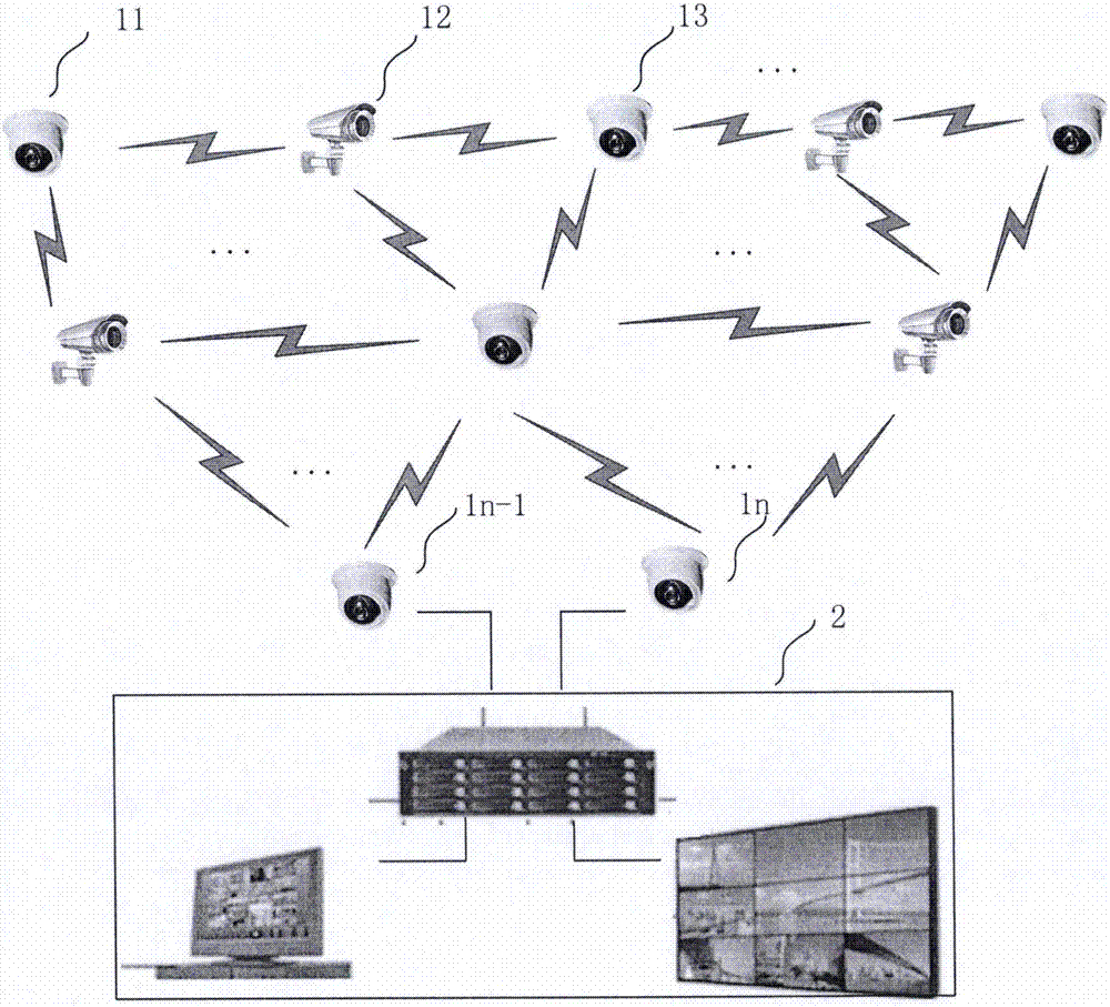
[0049] figure 1 It is a block diagram of the wireless monitoring system 100 according to the embodiment of the present invention. The wireless monitoring system 100 includes multimedia nodes 1-n connected via a wireless network; a monitoring center 2 for receiving and playing data transmitted by the multimedia nodes. The monitoring center 2 can receive the data of the multimedia nodes 1-n in a wireless or wired manner, and play and / or monitor the data through...


PUM


Abstract

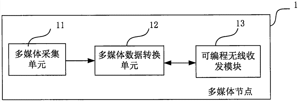
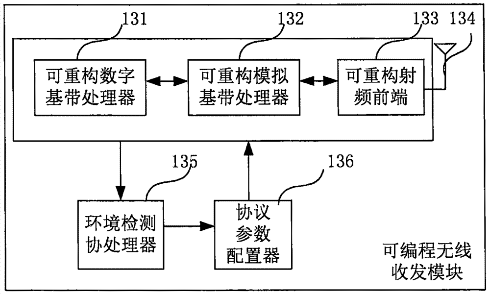
The invention discloses a wireless monitoring system. The wireless monitoring system comprises multimedia nodes which are connected through a wireless network; and each multimedia node comprises a multimedia information acquisition unit for acquiring multimedia information, a multimedia information conversion unit for converting the acquired multimedia information into multimedia code streams through coding and a programmable wireless receiving and transmitting unit for detecting the network environment where the node is located and configuring protocol parameters to receive and transmit the multimedia code streams wirelessly. By means of the wireless environment self-detection, protocol programming, RF front-end dynamic configuration and baseband unit reconfigurable technologies provided by the wireless monitoring system, it can be guaranteed that the overall wireless monitoring system achieves the good system security, the signal stability, the deployment convenience, the application practicability and the flexible expansibility in the multimedia signal transmission monitoring process.

Description

technical field [0001] The invention relates to a wireless monitoring system and method, in particular to a wireless monitoring system and method capable of detecting network environment and adaptively configuring network parameters. Background technique [0002] At present, people's demand for public safety is getting higher and higher, and many indoor and outdoor public places have been equipped with video surveillance systems to monitor the on-site environment. Once an abnormal situation occurs, security personnel can quickly discover it through the monitoring system and take timely action. [0003] With the continuous development of network intelligence, traditional video surveillance systems can no longer meet the needs of large-scale surveillance projects, mainly in complex wiring projects; the establishment of wired network surveillance systems must dig trenches and lay cables, so a lot of manpower and resources are required. Physical resources, and damage to the nat...

Claims


Application Information

Patent Timeline
Patent Type & Authority Applications(China)
IPC IPC(8): H04L12/24H04N7/18G08C17/02
CPCG08C17/02H04L41/04H04N7/18
Inventor 夏光武剑辉
Owner 北京中天鼎盛视讯科技有限公司
Learn More