
Object motion attitude perception method and system based on inertial sensor rigid body grid

An inertial sensor and motion attitude technology, applied in the field of inertial sensors, can solve the problem that the accuracy of motion attitude perception of inertial sensors cannot be satisfied

Active Publication Date: 2020-07-17
GUILIN UNIV OF ELECTRONIC TECH
View PDF7 Cites 0 Cited by
  • Summary
  • Abstract
  • Description
  • Claims
  • Application Information

AI Technical Summary

Problems solved by technology

[0003] What the present invention aims to solve is the problem that the motion posture perception accuracy of existing inertial sensors cannot meet the actual requirements, and provides a method and system for object motion posture perception based on inertial sensor rigid body grid

Method used


Image

  • Object motion attitude perception method and system based on inertial sensor rigid body grid

Examples


Embodiment Construction

[0028] In order to make the object, technical solution and advantages of the present invention clearer, the present invention will be further described in detail below in combination with specific examples and with reference to the accompanying drawings.

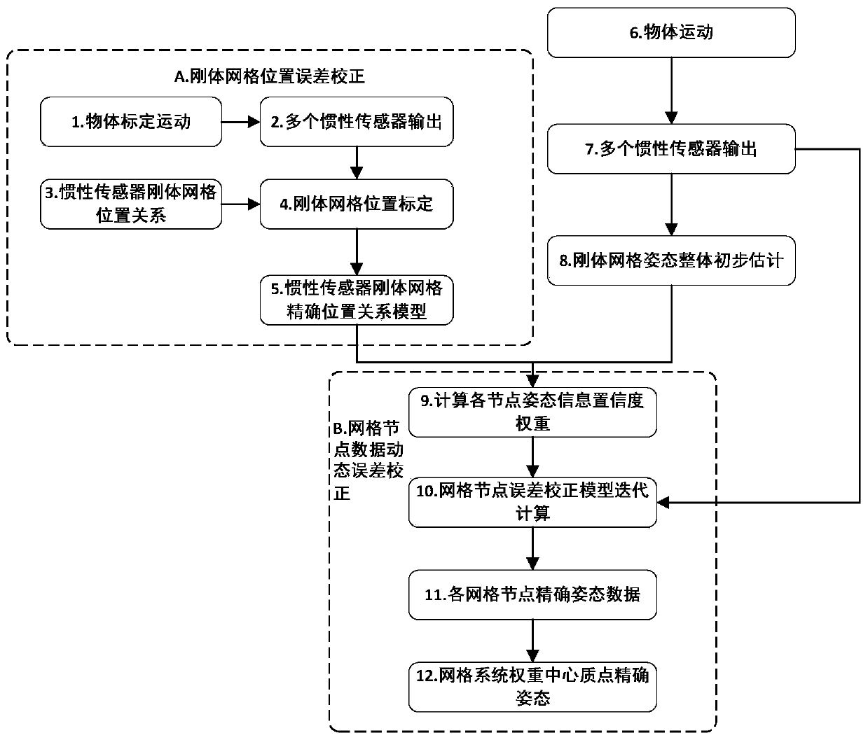
[0029] The object motion attitude perception system based on the inertial sensor rigid body grid is composed of a data processing unit and more than two inertial sensor nodes. Inertial sensor nodes constitute a peer-to-peer sensor rigid body grid network. Each inertial sensor node has a rigid spatial position relationship, and each grid node has a non-central peer relationship, so that the motion attitude data of a single inertial sensor can be , to estimate the motion attitude of other nodes, and provide a reference for error correction of other nodes. The inertial sensor node is responsible for sensing the motion posture data (acceleration, angular velocity, magnetic field vector, etc.), and transmits the motion posture da...


PUM


Abstract

The invention discloses an inertial sensor rigid grid based object motion attitude sensing method and system. A sensor rigid grid positioning technology, an adaptive weight distribution technology and a multi-inertial sensor information fusion technology are combined, multiple inertial sensor nodes are used to form an equal sensor grid network, attitude sensing data of the sensor nodes is analyzed and fused, and a complete motion posture of an objected attached to a grid system is calculated through position error correction of the rigid grids and dynamic error correction of the grid node data. By the arrangement, motion parameter sensing accuracy of an inertial sensor can be improved, and accurate sensing tracking of real-time motion trajectory and motion posture of the object can be realized; key steps of the method includes position error correction of the rigid grids and dynamic error correction of the grid node data.

Description

technical field [0001] The present invention relates to the technical field of inertial sensors, in particular to a method and system for sensing motion and attitude of an object based on rigid body grids of inertial sensors. Background technique [0002] At present, inertial sensors have been widely used in mobile electronic devices. By fusing the sensing data of accelerometers, gyroscopes, and magnetometers of inertial sensors, calculating the motion posture and trajectory of objects has become the main application field of inertial sensors. There are a wide range of application requirements in areas such as positioning, aircraft position and attitude perception in the air, and object motion and attitude detection. However, due to the limitations of inertial sensor technology, cost, accuracy, interference, cumulative error and other factors, the motion attitude perception accuracy of inertial sensors still cannot meet the accuracy requirements of realistic attitude monitor...

Claims


Application Information

Patent Timeline
Patent Type & Authority Patents(China)
IPC IPC(8): G01C21/16G01C25/00
CPCG01C21/16G01C25/005
Inventor 刘杰林科覃志松张纪元甘国宁卢艳梅姜虎成
Owner GUILIN UNIV OF ELECTRONIC TECH
Learn More