Electrical connectors for flat conductors

A technology of flat conductors and electrical connectors, applied in the direction of connections, circuits, coupling devices, etc., can solve the problems of not getting a click feeling, misidentifying the position of the operating lever, and difficult operation of the operating lever, and achieve the effect of preventing grinding

Active Publication Date: 2020-07-28
HIROSE ELECTRIC GROUP
View PDF7 Cites 0 Cited by
  • Summary
  • Abstract
  • Description
  • Claims
  • Application Information

AI Technical Summary

Problems solved by technology

As a result, the locus of the cam portion during the rotation of the operating lever differs from the normal locus, so that the desired operating feeling such as a click feeling cannot be obtained, for example, it may be difficult to operate the operating lever, and the position of the operating lever may be misidentified.

Method used


Image

  • Electrical connectors for flat conductors
  • Electrical connectors for flat conductors
  • Electrical connectors for flat conductors

Examples


no. 1 approach >

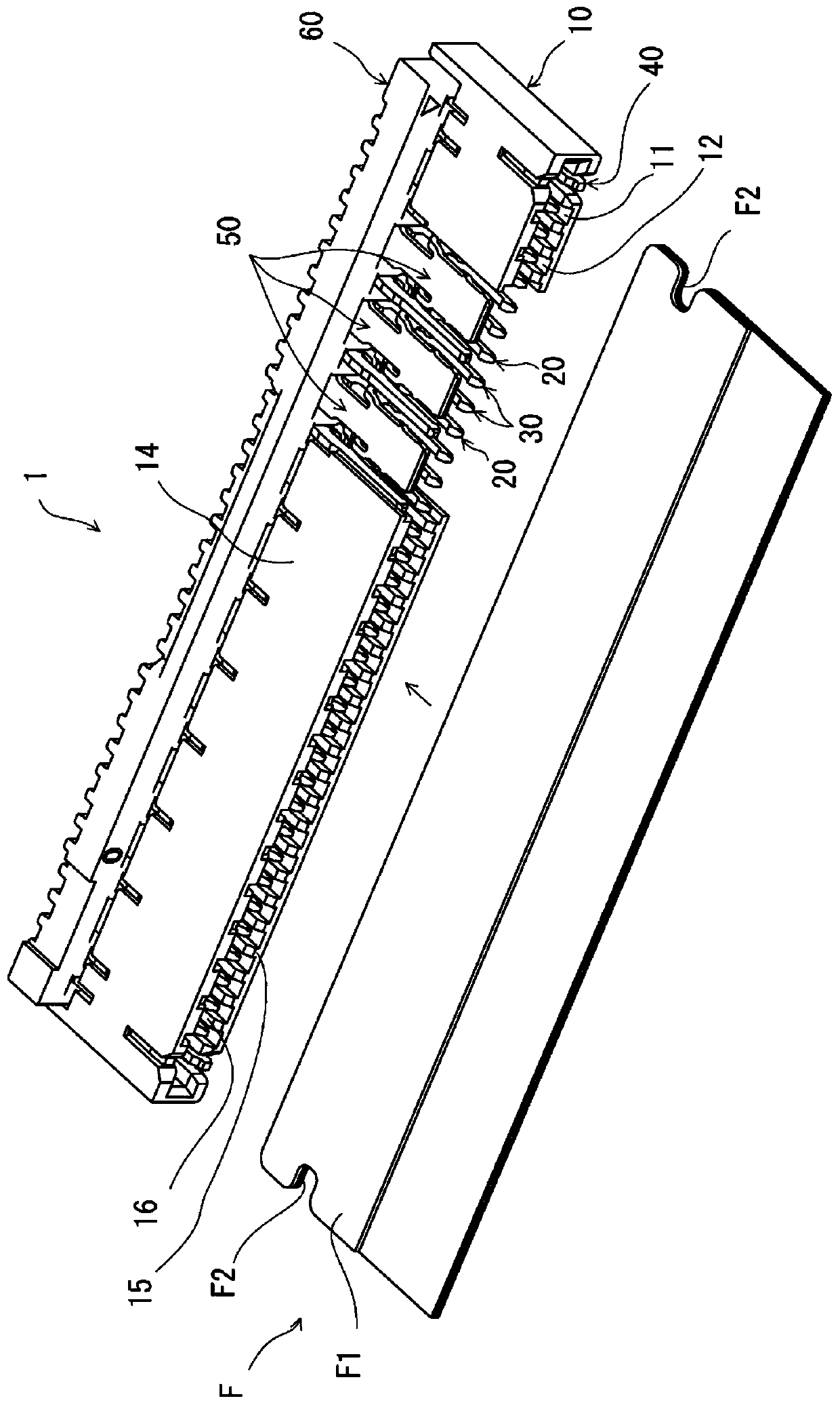
[0030] figure 1 It is an overall perspective view showing the flat conductor electrical connector 1 (hereinafter referred to as "connector 1") and the flat conductor F according to the present embodiment, and a part of the housing 10 described later is omitted. The connector 1 is disposed on a mounting surface of a circuit board (not shown), and the flat conductor F is inserted and removed in one direction parallel to the mounting surface, that is, the front-rear direction.

[0031] The flat conductor F is at its front end ( figure 1 The upper right edge part of the part close to the connector 1) has a connecting part with the above-mentioned connector 1, and faces rearward ( figure 1 Middle left bottom) extends long, but only the part up to the position immediately behind the connection part is shown in the figure, and the illustration of the part behind this position is omitted. With respect to the above-mentioned flat conductor F, in this embodiment, the coating on the lo...

no. 2 approach >

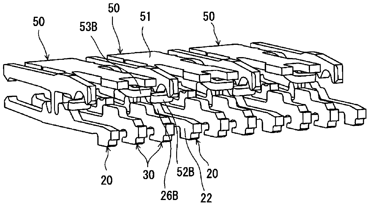
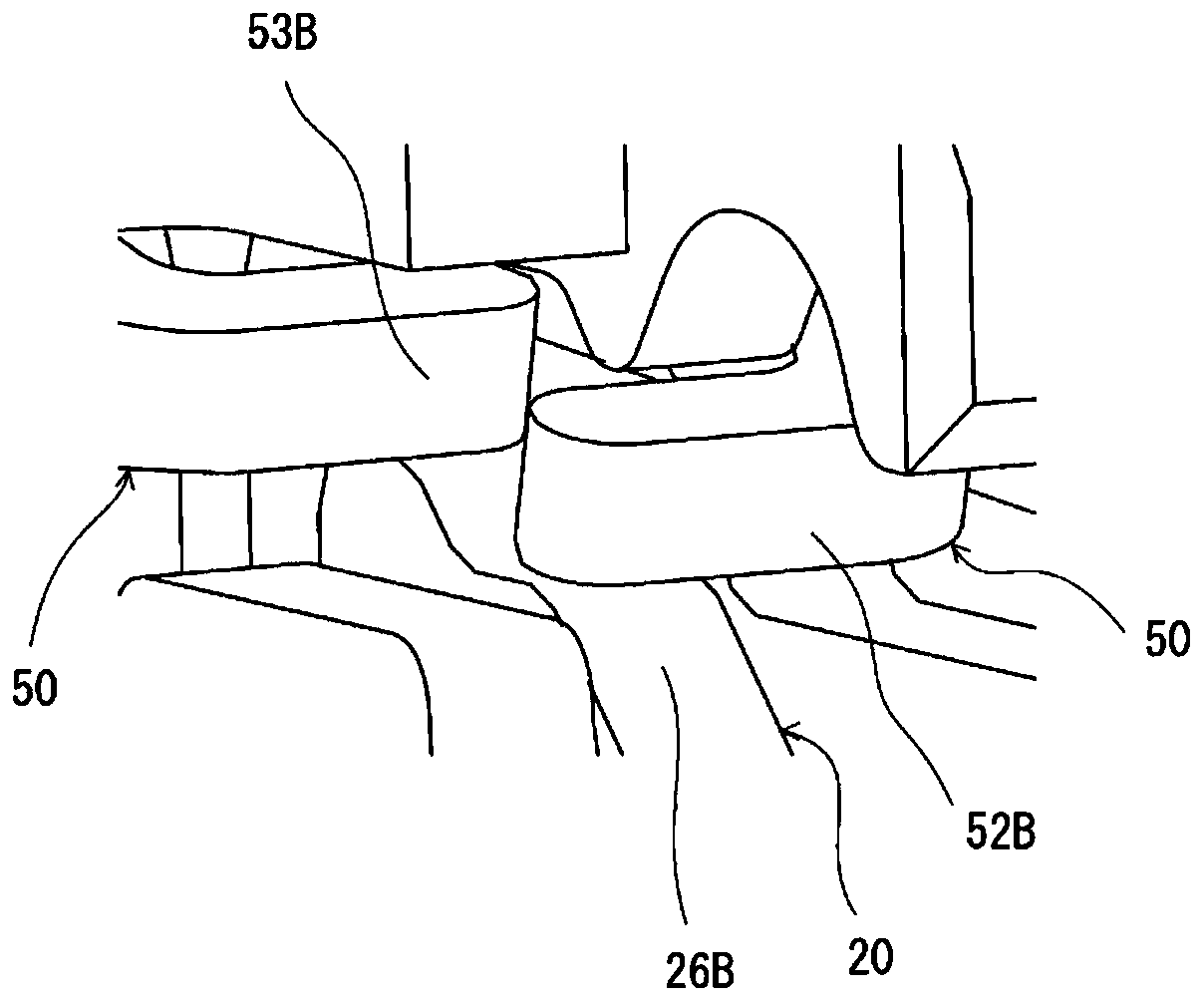
[0091] In the first embodiment, the restricting portion 15C is formed on the bottom wall 15 of the housing 10 in the terminal-free range in the direction of the terminal arrangement, and restricts the movable member 60 from descending by a predetermined amount or more. The lower end of the movable member in the non-terminal range is positioned lower than the lower end of other ranges without providing a restricting portion as in the first embodiment, thereby restricting the lowering of the movable member by a predetermined amount or more. In this regard, It is different from the first embodiment. In this embodiment, reference numerals with "100" added to the reference numerals in the first embodiment are assigned to parts corresponding to the first embodiment, and the differences from the first embodiment will be mainly described. .

[0092] Figure 10 It is an overall perspective view showing an electrical connector 101 for a flat conductor (hereinafter referred to simply a...


PUM


Abstract

The present invention provides an electrical connector for a flat conductor capable of maintaining an operational feeling close to a normal operating feeling for the operation of a movable member even when the cam portion of the movable member is ground due to the rotation of the movable member. The terminal (20) also has an upper arm (21) which is connected to the lower arm by a connecting portion (23) and extends in the front-rear direction except the lower arm (22). The force of the cam portion (65) and the pressure receiving part (24A) that can be elastically displaced upward; on the rear end side, it is used to elastically displace downward according to the elastic displacement of the pressure receiving part and press the flat conductor from above. The pressing part (25A) of (F), when the movable part is at least in the process of moving, at least a part of the specified non-terminal range constituting at least a part of the non-terminal range of the position different from the position of the terminal in the terminal arrangement direction, is biased downward from the normal position. The movable part can abut against the bottom wall in the up and down direction.

Description

technical field [0001] The present invention relates to an electrical connector for flat conductors arranged on a mounting surface of a circuit board and for plugging and pulling out of flat conductors. Background technique [0002] Such an electrical connector for a flat conductor is disclosed in Patent Document 1, for example. In the electrical connector for a flat conductor of Patent Document 1, a plurality of terminals are aligned and held in a housing, and an operation lever is rotatably supported by the housing. The operating lever is rotatable between an open position allowing the flat conductor to be inserted forward into the case, and a closed position increasing the contact pressure of the flat conductor to the terminal, and has a cam portion described later at the same position as each terminal. [0003] The terminal is a metal plate member that maintains a flat plate surface, is arranged in a direction perpendicular to the plate surface, has a lower arm extendin...

Claims


Application Information

Patent Timeline
Patent Type & Authority Patents(China)
IPC IPC(8): H01R12/70H01R12/89
CPCH01R12/70H01R12/89H01R12/78H01R12/88
Inventor 山嵜宽之平原恒
Owner HIROSE ELECTRIC GROUP
Why Eureka
Try Eureka