
formwork support for construction

A technology for form support and construction, which is applied to construction, building structure, and on-site preparation of building components, etc., can solve the problems of increasing the labor intensity of operators, reducing the use range of the form support, and high construction labor intensity, achieving Improve work efficiency, increase the scope of application, and the effect of a wide range of applications

Active Publication Date: 2019-11-01
江苏易明昌建设集团有限公司
View PDF6 Cites 0 Cited by
  • Summary
  • Abstract
  • Description
  • Claims
  • Application Information

AI Technical Summary

Problems solved by technology

[0002] In building construction, it is generally necessary to perform formwork work on specific concrete objects to ensure the stability of its shape. In the construction process of existing building formwork projects, it is necessary to consume wood as filling materials to support the formwork, and the construction labor intensity is high and the speed is slow. , Construction quality is not stable
[0003] The form supporter in the prior art requires manual adjustment, which increases the labor intensity of the operators and reduces the working efficiency; the form supporter in the prior art cannot adjust the support angle according to the shape of the formwork, thus greatly reducing the cost of the form supporter. Therefore, there is an urgent need for a formwork supporter for construction to solve the above-mentioned problems.

Method used


Image

  • formwork support for construction
  • formwork support for construction
  • formwork support for construction

Examples


Embodiment Construction

[0019] In order to make the technical means, creative features, goals and effects achieved by the present invention easy to understand, the present invention will be further described below in conjunction with specific embodiments.

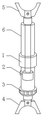
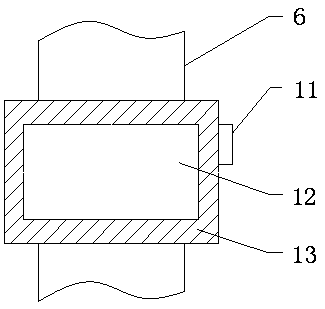
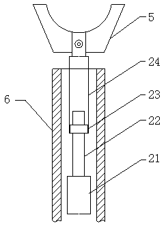
[0020] see Figure 1-Figure 4 , the present invention provides a technical solution: a formwork support for construction, including a main component, an energy-saving mechanism 1, a distance adjustment mechanism 2 and an angle adjustment mechanism 3, the main component consists of a device shell 6, an upper support base 5 and a lower support base 4, the upper support seat 5 is installed on the upper end surface of the distance adjustment mechanism 2, and the lower support seat 4 is assembled on the lower end surface of the angle adjustment mechanism 3.

[0021] The distance adjustment mechanism 2 is arranged in the device casing 6, the distance adjustment mechanism 2 is made up of a motor 21, a screw mandrel 22, a nut seat 23 and a push rod 24, th...


PUM


Abstract

The invention provides an architectural formwork erecting device. The architectural formwork erecting device comprises a device shell, an upper supporting base, a lower supporting base, a motor, a lead screw, a nut seat, an ejector pin, a connection shaft, clamping grooves, clamping fasteners, an adjusting handle and a groove body. The motor is installed in the device shell, the lead screw is connected with the motor through a coupler, the upper end of the lead screw is installed in the ejector rod which is connected with the lead screw through the nut seat, the upper end surface of the ejector rod is connected with the upper supporting base, the groove body is installed at the lower end of the outer surface of the device shell, the upper end of the connecting rod is installed in the device shell, the lower end surface of the connecting shaft is connected with the lower supporting base, the adjusting handle is installed in the groove body, the lower end of the adjusting handle is connected with the connecting shaft, the clamping fasteners are installed on the lower end surface of the adjusting handle, and the clamping grooves are formed in the upper end surface of the groove body. The architectural formwork erecting device is reasonable in structure, good in supporting effect and convenient to install, the working efficiency of operating personnel is improved, the application range is wide, and the reliability is high.

Description

technical field [0001] The invention relates to a formwork supporter for construction, which belongs to the field of construction equipment. Background technique [0002] In building construction, it is generally necessary to perform formwork work on specific concrete objects to ensure the stability of its shape. In the construction process of existing building formwork projects, it is necessary to consume wood as filling materials to support the formwork, and the construction labor intensity is high and the speed is slow. , Construction quality is unstable. [0003] The form supporter in the prior art requires manual adjustment, which increases the labor intensity of the operators and reduces the working efficiency; the form supporter in the prior art cannot adjust the support angle according to the shape of the formwork, thus greatly reducing the cost of the form supporter. Therefore, there is an urgent need for a form support for construction to solve the above-mentioned...

Claims


Application Information

Patent Timeline
Patent Type & Authority Patents(China)
IPC IPC(8): E04G11/48E04G25/06
CPCE04G11/48E04G25/065
Inventor 李涛伊超汤卜雄
Owner 江苏易明昌建设集团有限公司
Learn More