Novel dust catcher equipment

A dust collector and a new type of technology, applied in the parts, electrical components, coupling devices, etc. of the connection device, can solve the problems that the electric coupling head cannot be automatically ejected, the dust collector is damaged by power failure, and the power supply connection is unstable, so as to achieve stable power supply. The effect of good performance, safe and stable power supply, and simple structure

Inactive Publication Date: 2017-11-21
骆剑锋
View PDF0 Cites 7 Cited by
  • Summary
  • Abstract
  • Description
  • Claims
  • Application Information

AI Technical Summary

Problems solved by technology

[0002] At present, the electrification of the dust collector is mainly to insert the electrical connection head connected to the dust collector directly into the electrical connection hole of the power transmission frame. It can still be pulled out directly. When kicking and hitting the cable connected between the electrical connector and the dust collector by mistake, it will cause the electrical connector to detach from the electrical connector hole, resulting in a sudden power failure of the dust collector. Therefore, the existing The matching method has the risk of unstable power supply connection, and it is easy to cause sudden power failure and damage to the dust collector. Moreover, the electrical connector of the existing coordination method cannot automatically pop up, and a large force needs to be applied when the electrical connector is pulled out.

Method used


Image

  • Novel dust catcher equipment
  • Novel dust catcher equipment
  • Novel dust catcher equipment

Examples


Embodiment Construction

[0021] The preferred embodiments of the present invention will be described in detail below in conjunction with the accompanying drawings, so that the advantages and features of the present invention can be more easily understood by those skilled in the art, so as to define the protection scope of the present invention more clearly.

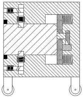
[0022] refer to Figure 1-5 A new type of dust collector equipment is shown, which includes an electrical connection head 1 and a power transmission frame 2. The electric connection head 1 is provided with an electric contact block 11 on the right end surface, and the upper and lower ends of the electrical connection head 1 are oppositely arranged. There are two locking grooves 12, the bottom of the power transmission frame 2 is provided with a column 45, the bottom of the column 45 is rotatably installed with a roller 46, and the power transmission frame 2 is conveniently moved by the roller 46, and the left end surface of the power transmission ...


PUM


Abstract

The invention discloses a new type of dust remover equipment, which includes an electric connection head and a power transmission frame. An electric contact block is arranged on the right end surface of the electric connection head, and two locks are oppositely arranged on the upper and lower ends of the electric connection head. The bottom of the power transmission frame is provided with a column, and the bottom of the column is rotatably installed with rollers. The left end surface of the power transmission frame is provided with a rightward expansion pin slot, and the upper and lower ends of the right part of the pin slot are opposite There are two pushing grooves communicating with the pin groove, and a pushing plate that expands into the two pushing grooves and can translate left and right in the two pushing grooves is arranged in the bolt groove, The invention has simple structure, good power supply stability, avoids electric shock accidents when pulling out the electric connector, and ensures people's life safety, and the whole device is safe and reliable in operation, with reasonable structural design, and the locking and unlocking operations of the electric connector Simple and convenient, suitable for promotion and use.

Description

technical field [0001] The invention relates to the field of dust collectors, in particular to a novel dust collector equipment. Background technique [0002] At present, the electrification of the dust collector is mainly to insert the electrical connection head connected to the dust collector directly into the electrical connection hole of the power transmission frame. It can still be pulled out directly. When kicking and hitting the cable connected between the electrical connector and the dust collector by mistake, it will cause the electrical connector to detach from the electrical connector hole, resulting in a sudden power failure of the dust collector. Therefore, the existing The matching method has the risk of unstable power supply connection, which is likely to cause sudden power failure and damage to the dust collector. Moreover, the electrical connector of the existing coordination method cannot automatically pop up, and a large force needs to be applied when the ...

Claims


Application Information

Patent Timeline
IPC IPC(8): H01R13/629H01R13/639H01R13/642H01R13/633
CPCH01R13/629H01R13/633H01R13/639H01R13/642
Inventor 骆剑锋
Owner 骆剑锋
Why Eureka
Try Eureka